This section specifies the architectural and functional elements of the GMPLS UNI on the 7750 SR or 7950 XRS nodes and the 1830 PSS node (which must be GMRE), and how they relate to one another. The architecture is illustrated in Figure 1.
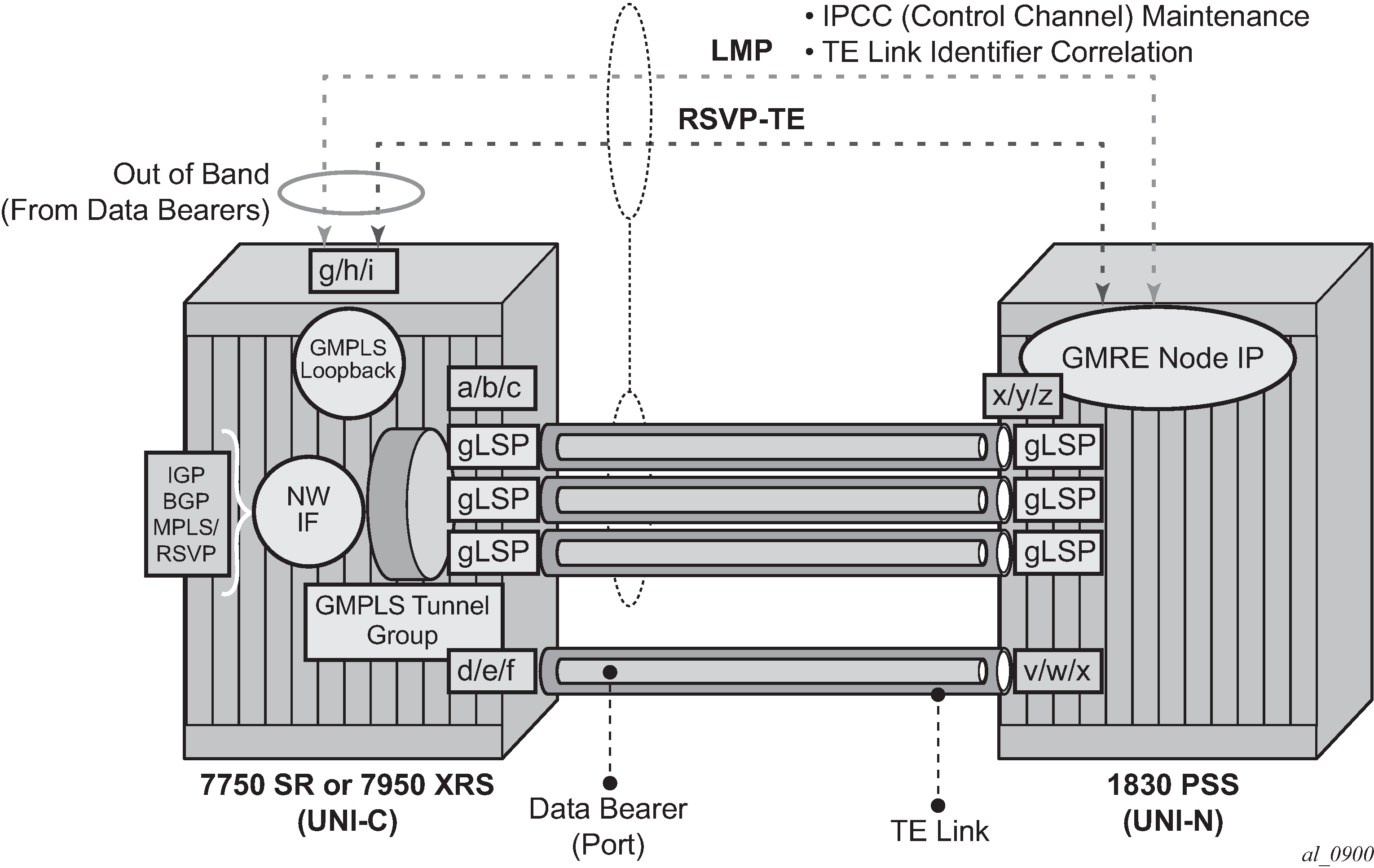
On the UNI-C side, the UNI consists of the following functional components:
A set of one or more data bearers between the UNI-C and UNI-N. Each data bearer maps to a black and white Ethernet network port.
A Traffic Engineering (TE) link (RFC 4202), represented by an identifier on the UNI-C and UNI-N nodes. This identifier is manually configured. A TE link maps to a single data bearer. There may be one or more TE links per UNI between a UNI-C and UNI-N pair.
An IP Control Channel (IPCC) between the UNI-C and UNI-N. The IPCC carries GMPLS control plane traffic between the two nodes and is separate from the links carrying user plane traffic. The IPCC may be native unencapsulated traffic, or it may be encapsulated in a GRE tunnel, and may use either an IP interface bound to a network Ethernet port on an Ethernet MDA/IMM or an OES Ethernet port on the CPM. This port is separate from the TE links. The IPCC carries the following two control protocols:
LMP — This is responsible for checking the correlation between the UNI-C/UNI-N and the TE link/Data Bearer identifiers, and maintaining the IPCC adjacency between the UNI-C and UNI-N.
RSVP-TE — RSVP-TE runs on the same network interface as LMP. The next hop from an RSVP-TE perspective is the UNI-N. RSVP-TE is used to establish and maintain a GMPLS LSP.
gLSP — The GMPLS LSP. At the UNI-C, this is a control plane object representing the TE-Link in the RSVP-TE control plane. Although this is an LSP, there is no explicit MPLS label in the data path at the UNI-C; the gLSP maps to a data bearer of the TE link to / from the UNI-N. When a gLSP is signaled to a far-end UNI-C node, the optical network establishes bidirectional connectivity between one of the data bearers in the TE link on the UNI-N at the ingress to the optical network, and one of the data bearers on the TE link on the egress UNI-N node connected to the far end UNI-C node.
Network Interface — When a gLSP is successfully established, a network interface can be bound to the gLSP. The network interface then uses the data bearer associated with the gLSP to forward traffic. This network interface can be used by any applicable protocol associated with an overlying IP/MPLS network. The network interface is bound to the gLSPs via a GMPLS tunnel group.
GMPLS Tunnel Group: a GMPLS tunnel group is a bundle of gLSPs providing an abstraction of the data bearers that are intended to be associated with one IP interface. A GMPLS tunnel group only exists on the UNI-C node and not on the 1830 PSS UNI-N node.
Although Figure 1 shows a single 7750 SR or 7950 XRS node connected to a single UNI-N (1830 PSS), it is possible to multi-home a router into more than one (usually two) UNI-Ns at the edge of the optical network. In this case, a separate IPCC, set of data bearers, and set of TE links, are required between the 7750 SR or 7950 XRS and each UNI-N.