Linear 1-for-1 protection of MPLS-TP LSPs is supported, as defined in RFC. This applies only to LSPs (not PWs).
This is supported edge-to-edge on an LSP, between two LERs, where normal traffic is transported either on the working LSP or on the protection LSP using a logical selector bridge at the source of the protected LSP.
At the sink LER of the protected LSP, the LSP that carries the normal traffic is selected, and that LSP becomes the working LSP. A protection switching coordination (PSC) protocol coordinates between the source and sink bridge, which LSP is used, as working path and protection path. The PSC protocol is always carried on a G-ACh on the protection LSP.
The system supports single-phased coordination between the LSP endpoints, in which the initiating LER performs the protection switchover to the alternate path and informs the far-end LER of the switch.
Bidirectional protection switching is achieved by the PSC protocol coordinating between the two end points to determine which of the two possible paths (that is the working or protect path), transmits user traffic at any specific time.
It is possible to configure non-revertive or revertive behavior. For non-revertive, the LSP does not switch back to the working path when the PSC switchover requests end, while for revertive configurations, the LSP always returns back to the working path when the switchover requests end.
The following figures illustrate the behavior of linear protection in more detail.
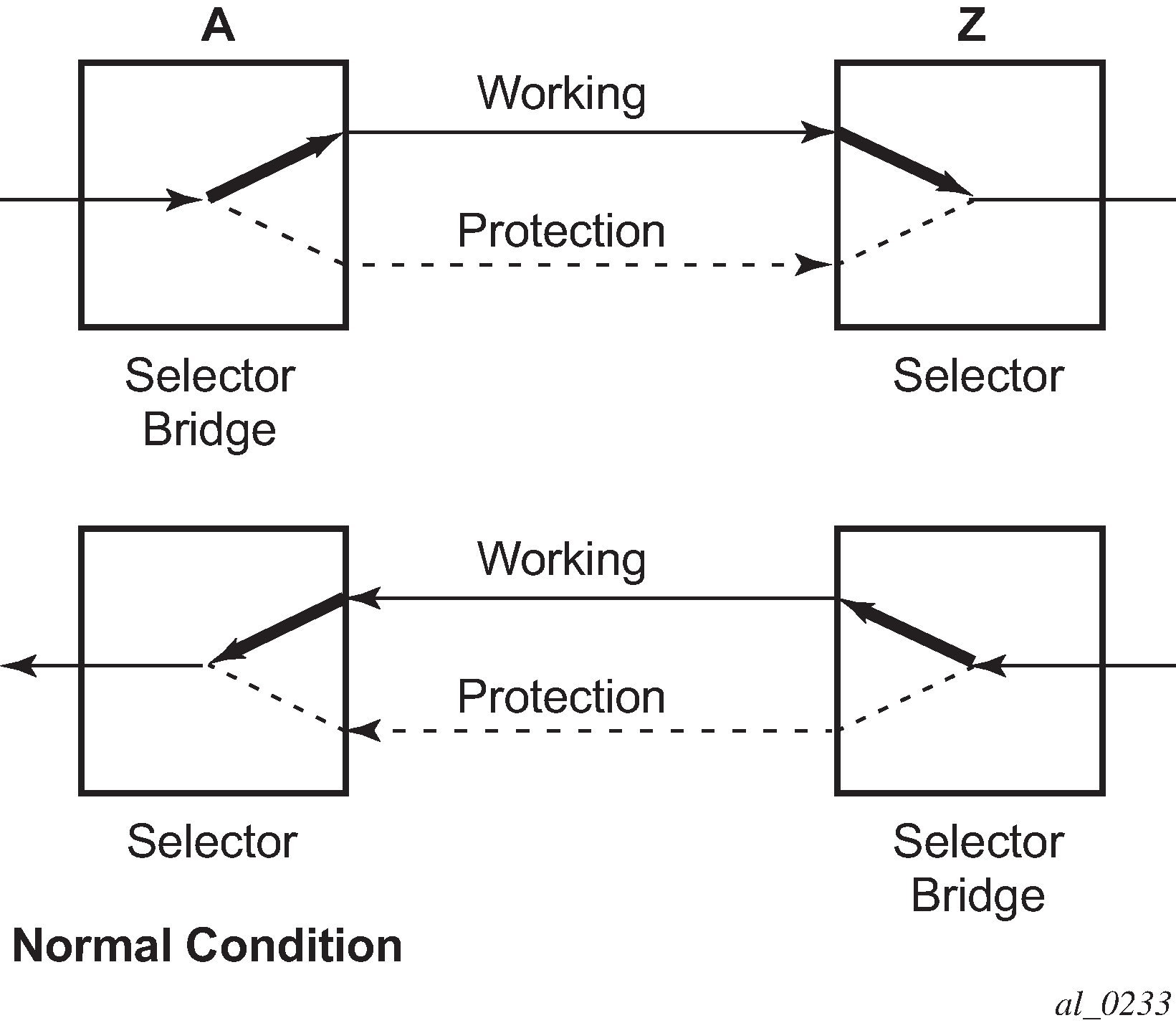
In normal condition, user data packets are sent on the working path on both directions, from A to Z and Z to A.
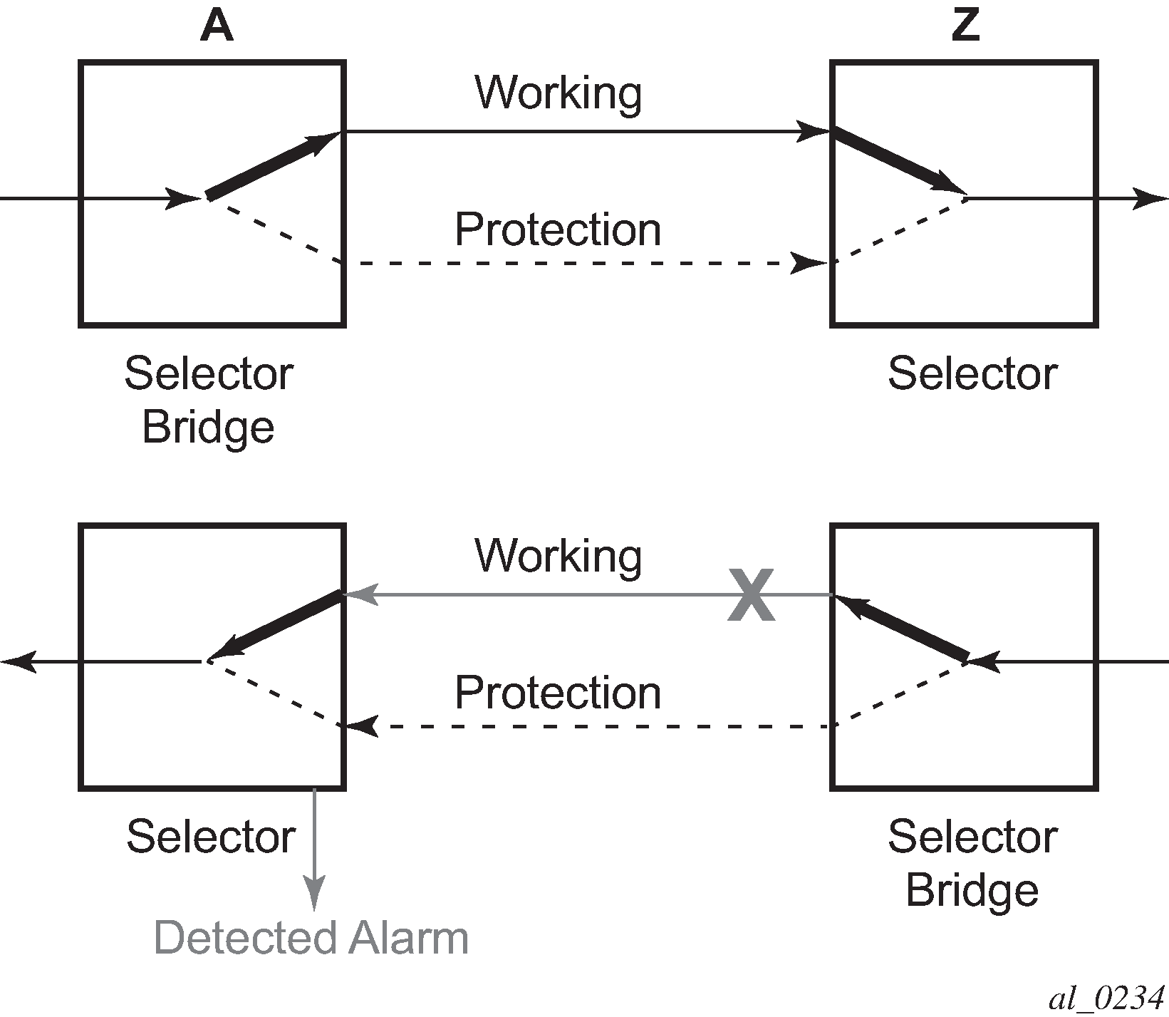
A defect in the direction of transmission from node Z to node A impacts the working connection Z-to-A, and initiates the detection of a defect at the node A.
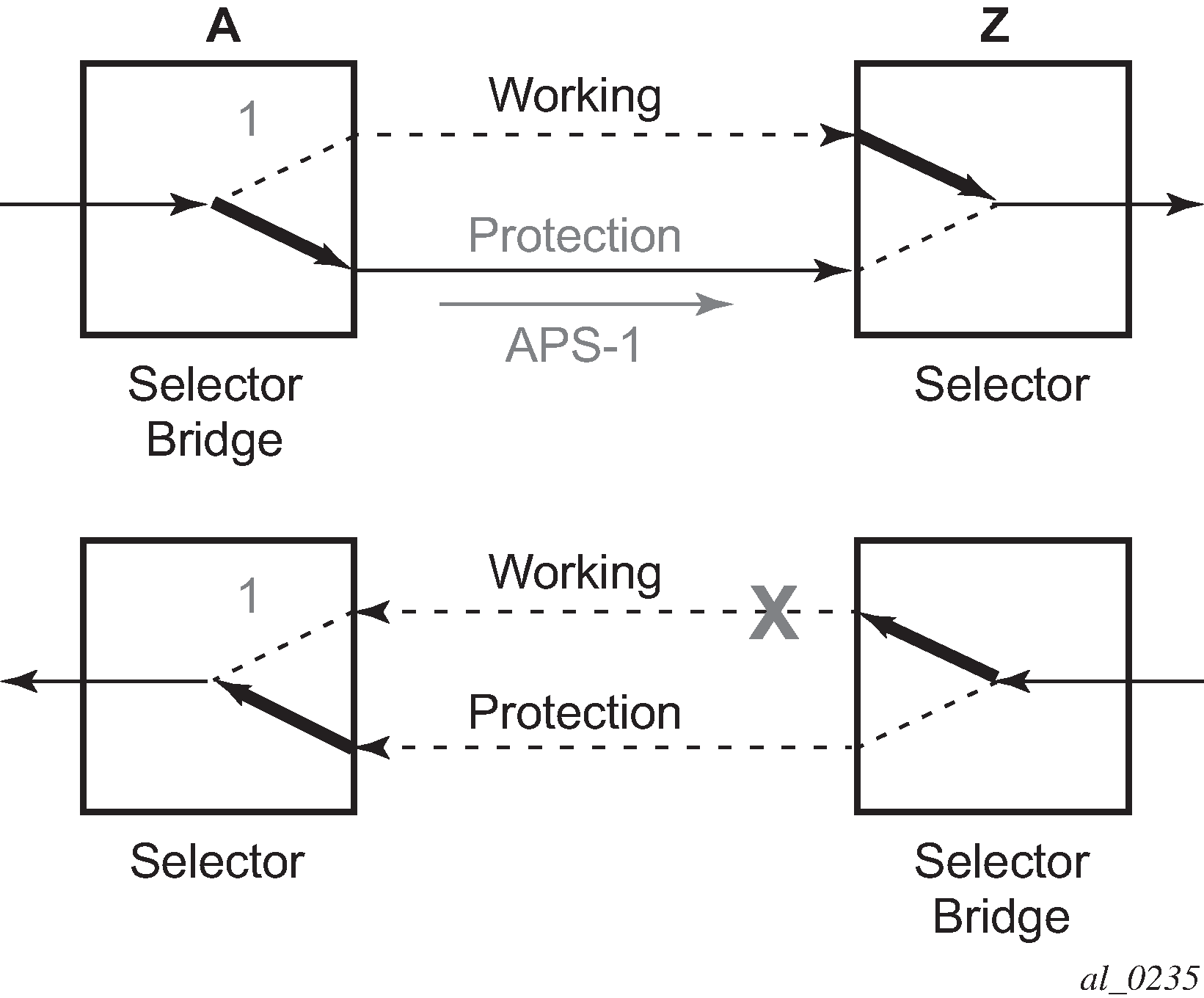
The unidirectional PSC protocol initiates protection switching: the selector bridge at node A is switched to protection connection A-to-Z and the selector at node A switches to protection connection Z to-A. The PSC packet, sent from node A to node Z, requests a protection switch to node Z.
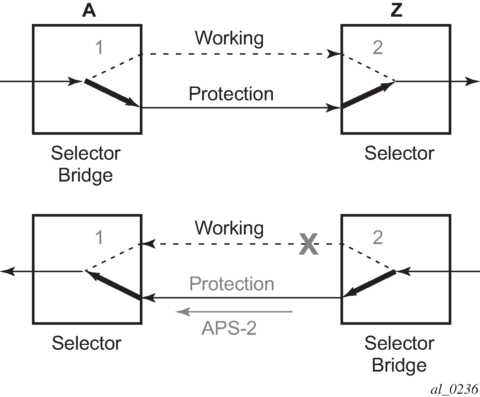
After node Z validates the priority of the protection switch request, the selector at node Z is switched to protection connection A-to-Z and the selector bridge at the node Z is switched to protection connection Z-to-A. The PSC packet, sent from node Z to node A, is used as acknowledge, informing node A about the switching.
If BFD CC or CC/CV OAM packets are used to detect defects on the working and protection paths, they are inserted on both working and protection paths. Packets are sent whether the path is selected as the currently active path. Linear protection switching is also triggered on receipt of an AIS with the LDI bit set.
The following operator commands are supported:
Forced Switch
Manual Switch
Clear