MPLS-TP is designed for use both with, and without, a control plane. MPLS-TP therefore specifies a set of identifiers that can be used for objects in either environment. This includes a path and maintenance identifier architecture comprising Node, Interface, PW and LSP identifiers, Maintenance Entity Groups (MEGs), Maintenance End Points (MEPs) and Maintenance Intermediate Points (MIPs). These identifiers are specified in RFC6370.
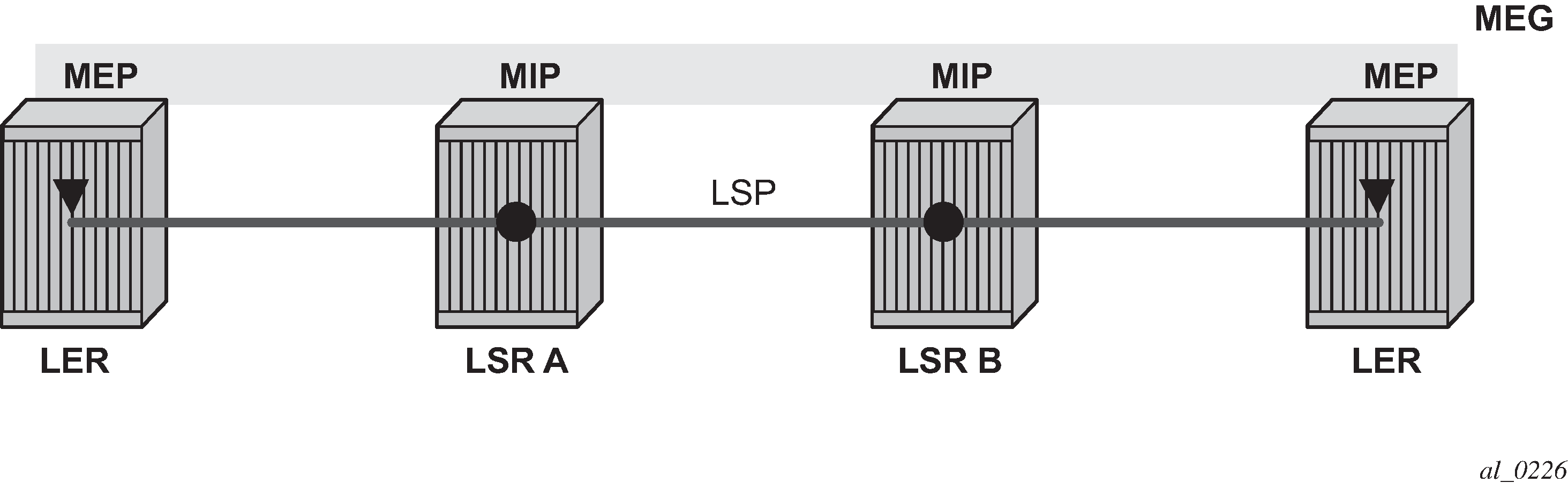
MPLS-TP OAM and protection switching operates within a framework that is designed to be similar to existing transport network maintenance architectures. MPLS-TP introduces concept of maintenance domains to be managed and monitored. In these, Maintenance Entity Group End Points (MEPs) are edges of a maintenance domain. OAM of a maintenance level must not leak beyond corresponding MEP and so MEPs typically reside at the end points of LSPs and PWs. Maintenance Intermediate Points (MIPS) define intermediate nodes to be monitored. Maintenance Entity Groups (MEGs) comprise all the MEPs and MIPs on an LSP or PW.
Both IP-compatible and ICC (ITU-T carrier code) based identifiers for the above objects are specified in the IETF, but only the IP-compatible identifiers defined in RFC6370 are supported.
SR OS supports the configuration of the following node and interface related identifiers:
Global_ID: this is similar to the global ID that can be configured for Dynamic MS-PWs. However, in MPLS-TP this should be set to the AS# of the node. If not explicitly configured, then it assumes the default value of 0. In SR OS, the source Global ID for an MPLS-TP Tunnel is taken to be the Global ID configured at the LER. The destination Global ID is optional in the tunnel configuration. If it is not configured, then it is taken as the same as the source Global ID.
Node_ID: this is a 32-bit value assigned by the operator within the scope of the Global_ID. The system supports the configuration of an IPv4 formatted address <a.b.c.d> or an unsigned 32-bit integer for the MPLS-TP Node ID at each node. The node ID must be unique within the scope of the global ID, but there is no requirement for it to be a valid routable IP address. Indeed, a node-id can represent a separate IP-compatible addressing space that may be separate from the IP addressing plan of the underlying network. If no node ID is configured, then the node ID is taken to be the system interface IPv4 address of the node. When configuring a tunnel at an LER, either an IPv4 or an unsigned integer Node ID can be configured as the source and destination identifiers, but both ends must be of the same type.
IF_ID: this is an MPLS-TP section layer identifier at the MPLS interface level. On the router, this is used to provide an identifier for the LSP-Trace DSMAP when an IP identifier is not available. The IF_ID is a 64-bit identifier of an MPLS-TP interface on a node that is unique within the scope of a Global_ID. It is composed of the Node_ID and the IF_Num. The IF_Num is a node-wide unique identifier for an MPLS-TP interface. On the router, this is primarily used for supporting the DSMAP TLV in LSP Trace using MPLS-TP identifiers with unnumbered MPLS-TP interfaces.
Statically configured LSPs are identified using GMPLS-compatible identifiers with the addition of a Tunnel_Num and LSP_Num. As in RSVP-TE, tunnels represent, for example, a set of working and protect LSPs. These are GMPLS-compatible because GMPLS chosen by the IETF as the control plane for MPLS-TP LSPs, although this is not supported in Release 11.0 of the software. PWs are identified using a PW Path ID which has the same structure as FEC129 AII Type 2.
SR OS derives the identifiers for MEPs and MIPs on LSPs and PWs based on the configured identifiers for the MPLS-TP Tunnel, LSP or PW Path ID, for use in MPLS-TP OAM and protection switching, as per RFC6370.
The information models for LSPs and PWs are illustrated in Figure 2 and Figure 3. The figures use the terminology defined in RFC6370.
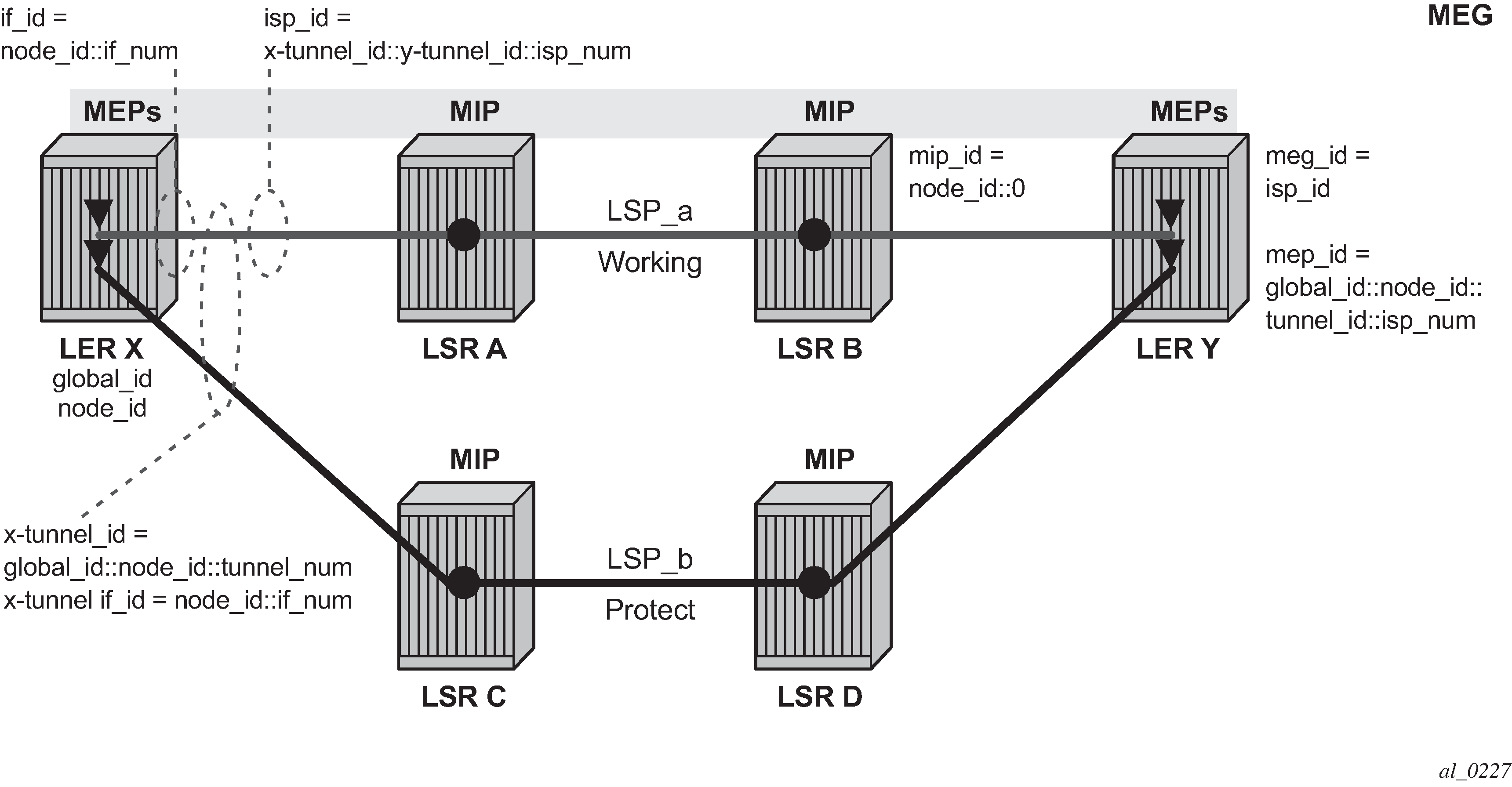
The MPLS-TP Tunnel ID and LSP ID are not to be confused with the RSVP-TE tunnel ID implemented on the router system. Table 1 shows how these map to the X and Y ends of the tunnel shown in Figure 2 for the case of co-routed bidirectional LSPs.
RSVP-TE Identifier |
MPLS-TP Maintenance Identifier |
|---|---|
Tunnel Endpoint Address |
Node ID (Y) |
Tunnel ID (X) |
Tunnel Num (X) |
Extended Tunnel ID |
Node ID (X) |
Tunnel Sender Address |
Node ID (X) |
LSP ID |
LSP Num |
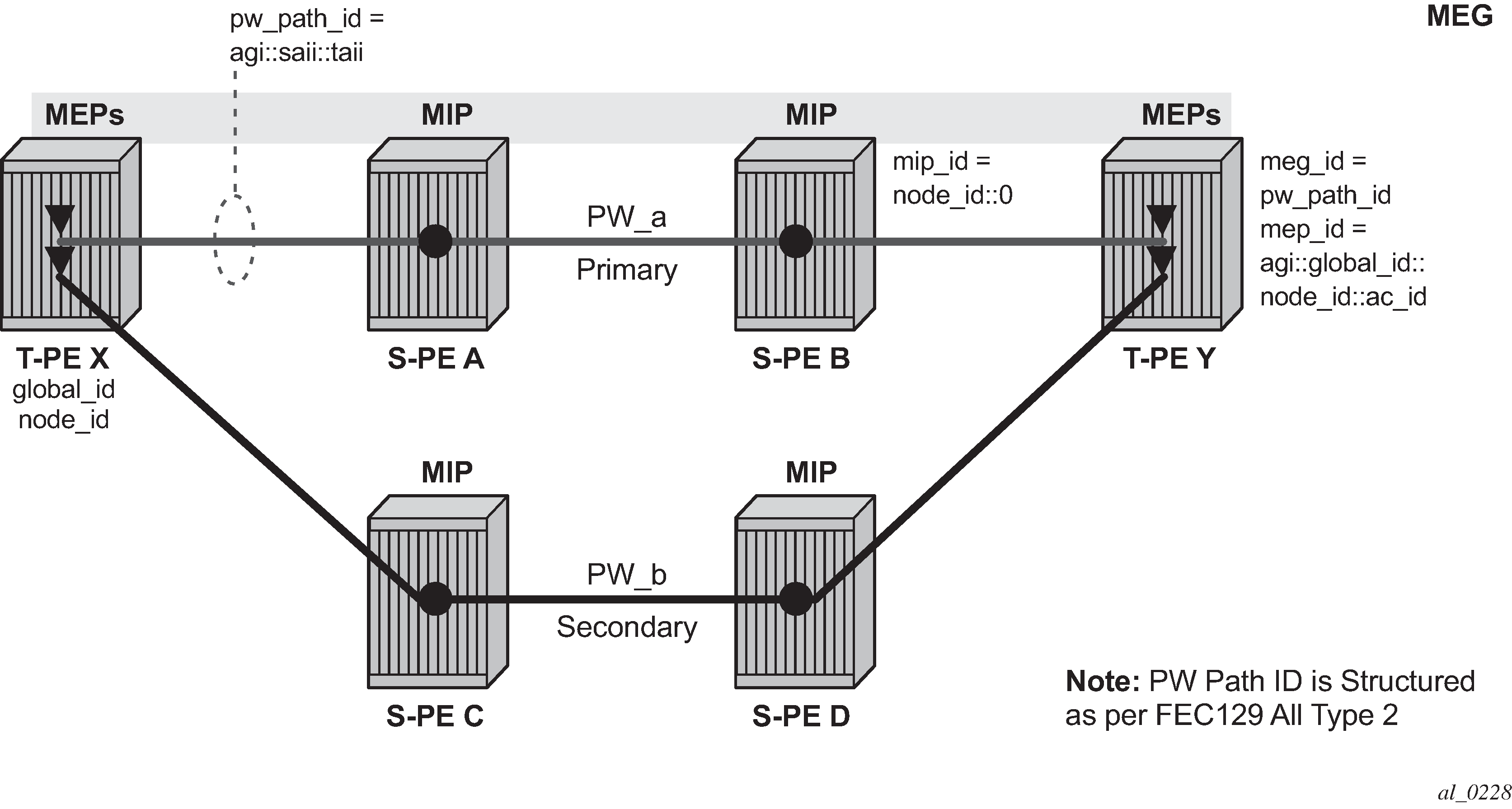
In the PW information model shown in Figure 3, the MS-PW is identified by the PW Path ID that is composed of the full AGI:SAII:TAII. The PW Path ID is also the MEP ID at the T-PEs, so a user does not have to explicitly configure a MEP ID; it is automatically derived by the system. For MPLS-TP PWs with static labels, although the PW is not signaled end-to-end, the directionality of the SAII and TAII is taken to be the same as for the equivalent label mapping message that is from downstream to upstream. This is to maintain consistency with signaled pseudowires using FEC 129.
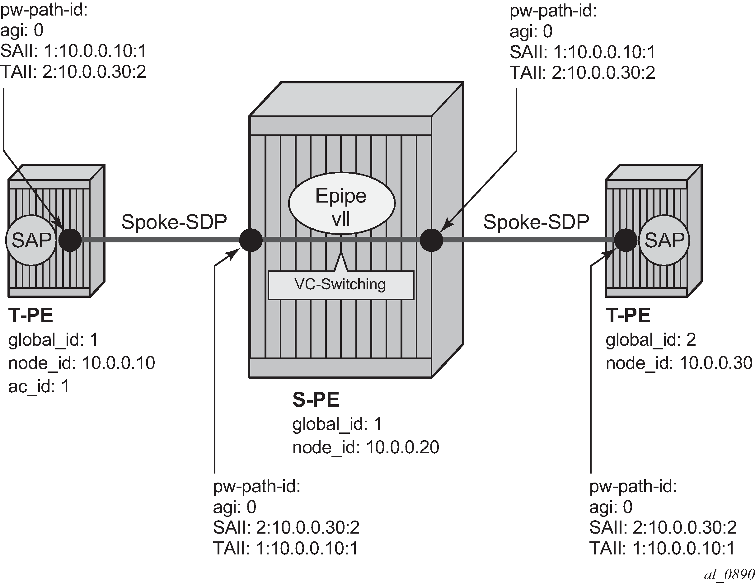
On the system, an S-PE for an MS-PW with static labels is configured as a pair of spoke SDPs bound together in an VLL service using the VC-switching command. Therefore, the PW Path ID configured at the spoke SDP level at an S-PE must contain the Global-ID, Node-ID, and AC-ID at the far end T-PEs, not the local S-PE. The ordering of the SAII:TAII in the PW Path ID where static PWs are used should be consistent with the direction of signaling of the egress label to a spoke SDP forming that segment, if that label were signaled using T-LDP (in downstream unsolicited mode). VCCV Ping checks the PW ID in the VCCV Ping echo request message against the configured PW Path ID for the egress PW segment.
Figure 4 shows an example of how the PW Path IDs can be configured for a simple two-segment MS-PW.