This section details the supported recovery reference models. These models are based on the mechanisms specified in RFC 4872 and RFC 4873.
Figure 1 presents a generalized reference model in which the 7750 SR or 7950 XRS UNI-C nodes are dual-homed at the link layer to the 1830 PSS UNI-N nodes. Not all elements of this architecture may be required in all deployment cases.
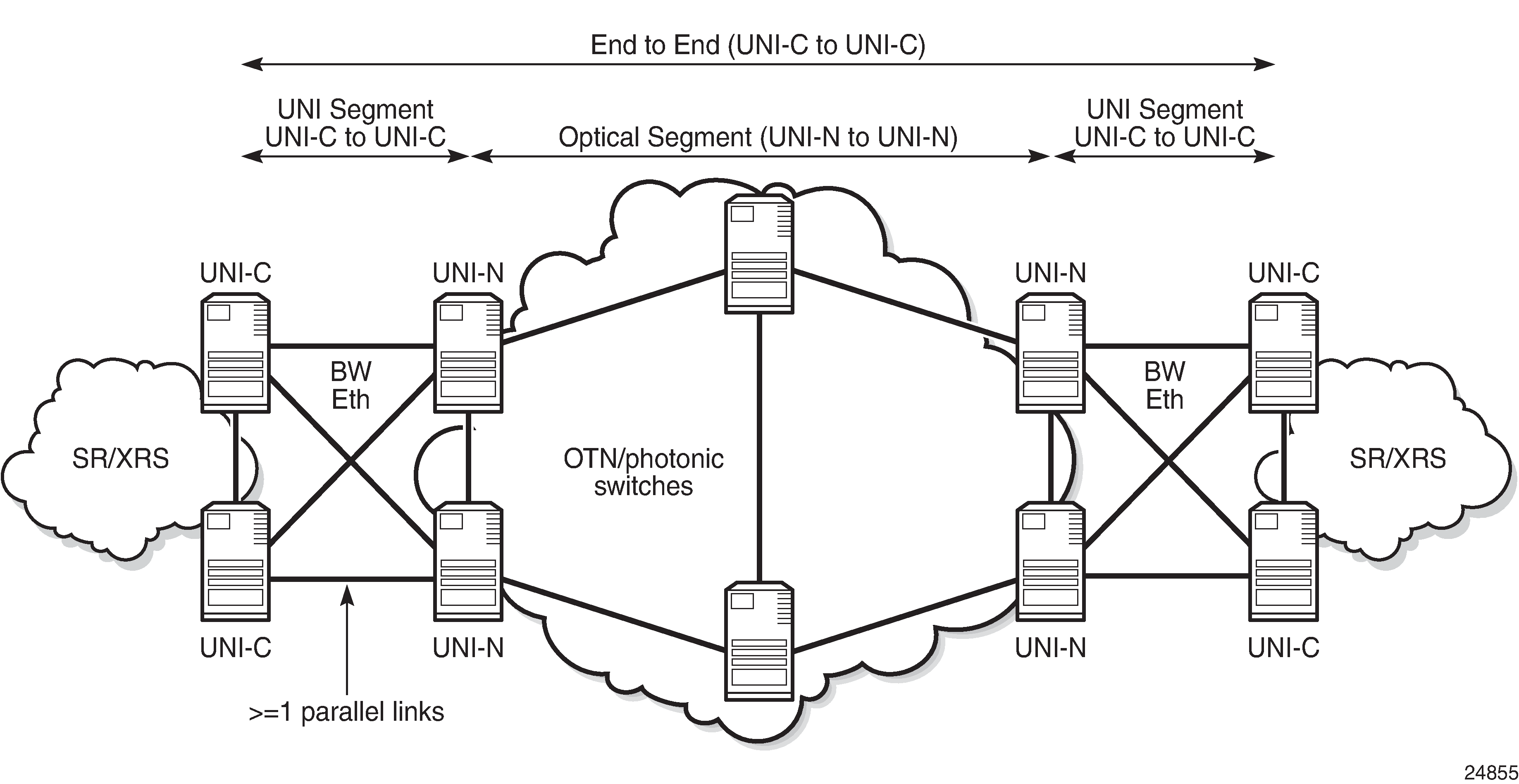
This reference model includes two 7750 SR or 7950 XRS nodes, each hosting a UNI-C function, at the edge of each IP network facing two 1830 PSS nodes, each hosting a UNI-N function. A full mesh of black and while Ethernet links interconnects neighboring UNI-C nodes and UNI-N nodes. Parallel links may exist, so that a specific 7750 SR or 7950 XRS UNI-C is connected to a neighbor 1830 PSS UNI-N by more than one Ethernet link.
Each router hosting a UNI-C has an IPCC to each of the two 1830 PSS UNI-Ns. Likewise, each 1830 PSS hosting UNI-N has an IPCC to both of the 7750 SR or 7950 XRS UNI-Cs that it is connected to. IPCCs only exist between UNI-C and UNI-N nodes, and not between UNI-C nodes. A control plane (LMP and RSVP) adjacency therefore exists between each UNI-C and it's corresponding UNI-Ns.
Recovery in the following domains is supported in the following locations:
End to End — Between the 7750 SR or 7950 XRS UNI-C nodes at each end of a gLSP.
Optical Segment — Between 1830 PSS UNI-N nodes at each edge of the optical network.
The following subsections detail some example recovery options that are possible using either GMPLS, or a combination of GMPLS mechanisms and mechanisms in the overlay IP network. Note that some of the functionality shown in one of the scenarios can be used in combination with functionality in another scenario, for example optical SRLG diversity.
The objective of GMPLS here is to minimize the disruption to the overlay IP network while simultaneously maximizing the utilization of both the gLSPs and the resources in the underlying optical network (or UNI links).