Prerequisites
Stitching in data-plane from the LDP-to-SR direction is based on the LDP module monitoring the TTM for a SR tunnel of a prefix matching an entry in the LDP TTM export policy.
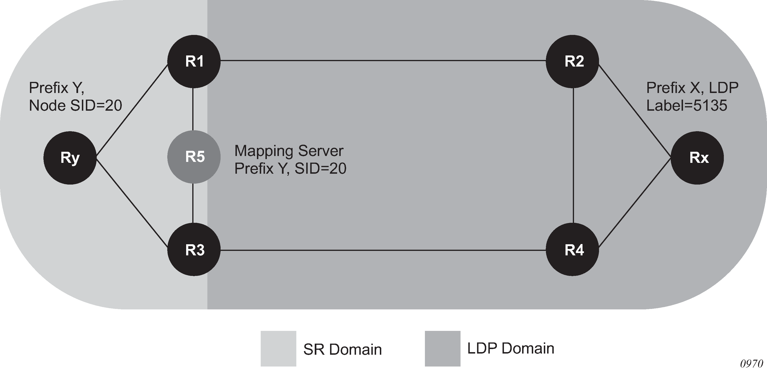
In Figure 1, the boundary router R1 performs the following procedure to effect stitching:
- Router R1 is at the boundary between an SR domain and LDP domain and is configured to stitch between SR and LDP.
- Link R1-R2 is LDP-enabled, but router R2 does not support SR (or SR is disabled).
- Router R1 receives a prefix-SID sub-TLV in an IS-IS IP reachability TLV originated by router Ry for prefix Y.
- R1 resolves the prefix-SID and programs an NHLFE on the link toward the next-hop in the SR domain. R1 programs an SR ILM and points it to this NHLFE.
- Because R1 is programmed to stitch LDP to SR, the LDP in R1 discovers in TTM the SR tunnel to Y. LDP programs an LDP ILM and points it to the SR tunnel. As a result, both the SR ILM and LDP ILM now point to the SR tunnel, one via the SR NHLFE and the other via the SR tunnel endpoint.
- R1 advertises the LDP FEC for the prefix Y to all its LDP peers. R2 is now able to install a LDP tunnel toward Ry.
-
If R1 finds multiple SR tunnels to destination prefix Y, it uses the following
steps of the TTM tunnel selection rules to select the SR tunnel.
- R1 selects the tunnel from the lowest preference IGP protocol.
- Select the protocol using the default TTM protocol preference.
- Within the same IGP protocol, R1 uses the lowest instance ID to select the tunnel.
-
If the user concurrently configured the from protocol
ospf, from protocol isis, and from
protocol bgp statements in the same LDP tunnel table export
policy, or did not include the from statement but added a default action of
accept, R1 selects the tunnel to destination prefix Y to stitch the LDP ILM to
using the TTM tunnel selection rules:
- R1 selects the tunnel from the lowest preference protocol.
- If any two or all of IS-IS, OSPF, and BGP protocols have the same preference, then R1 selects the protocol using the default TTM protocol preference.
- Within the same IGP protocol, R1 uses the lowest instance ID to select the tunnel.
Note:If R1 has already resolved a LDP FEC for prefix Y, it has an ILM for it, but this ILM is not be updated to point toward the SR tunnel. This is because LDP resolves in RTM first before going to TTM and, therefore, prefers the LDP tunnel over the SR tunnel. Similarly, if an LDP FEC is received after the stitching is programmed, the LDP ILM is updated to point to the LDP NHLFE because LDP can resolve the LDP FEC in RTM.
- The user enables SR in R2. R2 resolves the prefix SID for Y and installs the SR ILM and the SR NHLFE. R2 is now able of forwarding packets over the SR tunnel to router Ry. No processing occurs in R1 because the SR ILM is already programmed.
- The user disables LDP on the interface R1-R2 (both directions) and the LDP FEC ILM and NHLFE are removed in R1. The same occurs in R2 which can then only forward using the SR tunnel toward Ry.