Interaction points between the PXC traffic and non-PXC traffic in the FC depends on the configured PXC type. Figure: Interaction between PXC and non-PXC traffic shows this interaction as the traffic enters the egress forwarding path from the fabric tap (T). This traffic consists of non-PXC traffic (1) destined for the egress faceplate ports and PXC traffic (2) that is sent (cross-connected) to the ingress forwarding path (P) within the same forwarding complex. Regular ingress traffic from the faceplate ports (3) is added to the stream and merged into the same ingress forwarding path as the PXC traffic.
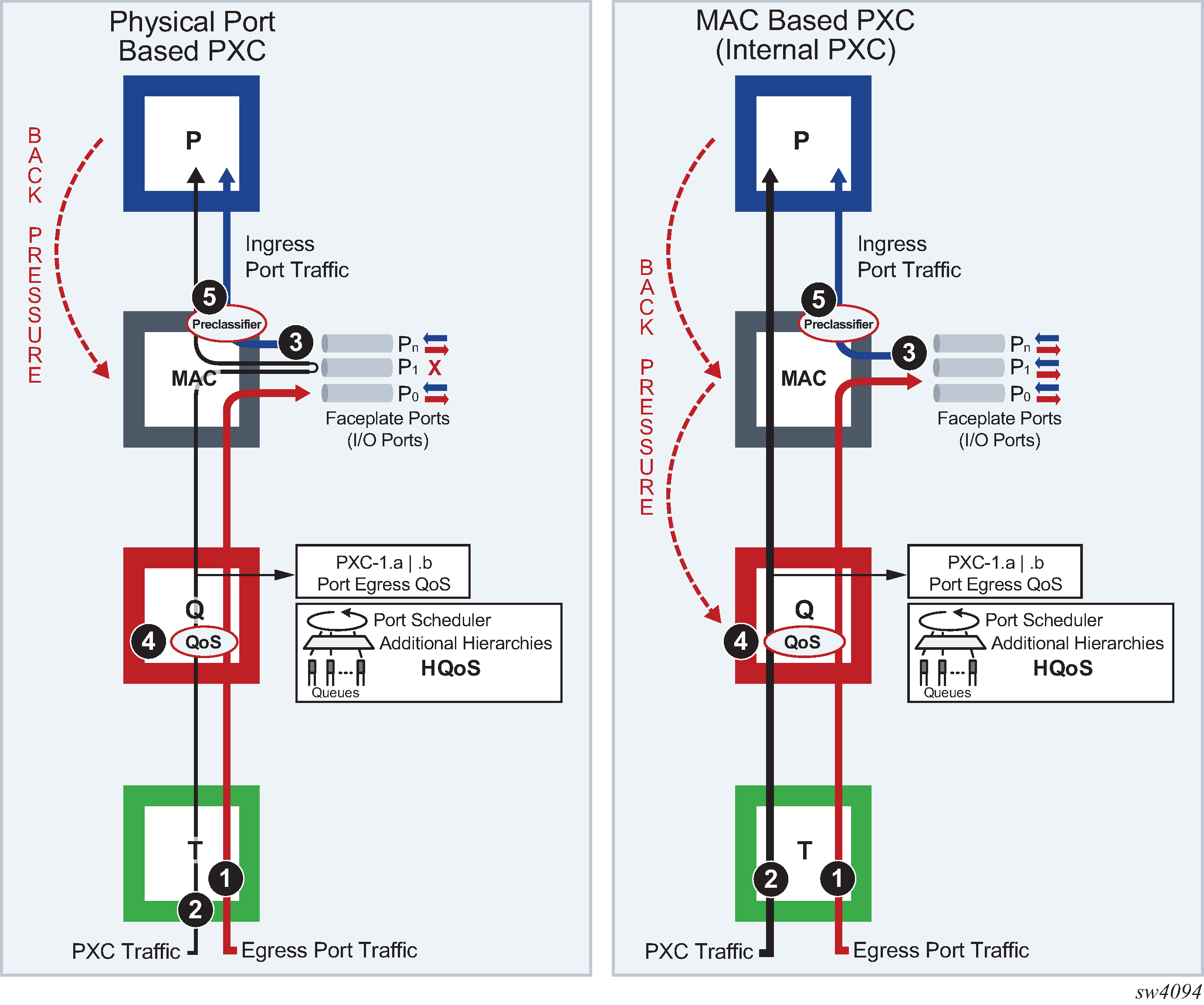
The physical port-based PXC configuration on the left side of Figure: Interaction between PXC and non-PXC traffic, shows interaction of the three traffic streams on the forwarding complex with a PXC based on the faceplate ports. To manage congestion, the user-configured input can be exserted in points 4 and 5.
Point 4 represents regular egress QoS in the traffic manager (Q) applied to an egress port. In this setup, the faceplate port P1 is reserved for PXC traffic which is represented by the two sub ports (PXC sub-ports pxc-id.a and pxc-id.b). Egress QoS is applied to each PXC subport.
 pxc-id      - pxc-<id>.<sub-port>
                pxc            - keyword
                id             - [1..64]
                sub-port       - [a..b]
Point 5 represents a pre-classifier in the MAC chip that manages ingress bandwidth if transient bursts occur in the ingress datapath (P), which then exserts back pressure toward the MAC. During congestion, the pre-classifier arbitrates between regular ingress traffic from the faceplate ports and the PXC traffic.
The MAC-based PXC configuration on the right side of Figure: Interaction between PXC and non-PXC traffic shows the traffic flow in the FC with the MAC-based PXC. Similar to the previous case, the existing egress QoS in the traffic manager (Q) in point 4 is applied to the egress ports. However, the egress port in the PXC case is not a faceplate port but instead it is represented by the configured loopback in the MAC chip. This loopback is configured with the maximum bandwidth using the configure card id xiom xiom-slot mda id xconnect mac id loopback id command. The congestion management logic with internal PXC diverges from the previous scenario because the PXC traffic is moved through the MAC chip straight to the ingress datapath (P), bypassing the egress faceplate ports. Therefore, the pre-classifier in point 5 has no effect on PXC traffic. Any congestion in the (P) and MAC is managed in the traffic manager (Q) at point 4, as a result of the back pressure from the (P) and MAC toward the (Q).