BGP-EVPN control plane for EVPN-VPWS
EVPN-VPWS uses route-type 1 and route-type 4; it does not use route-types 2, 3 or 5. Figure: EVPN-VPWS BGP extensions shows the encoding of the required extensions for the Ethernet A-D per-EVI routes. The encoding follows the guidelines described in RFC 8214.
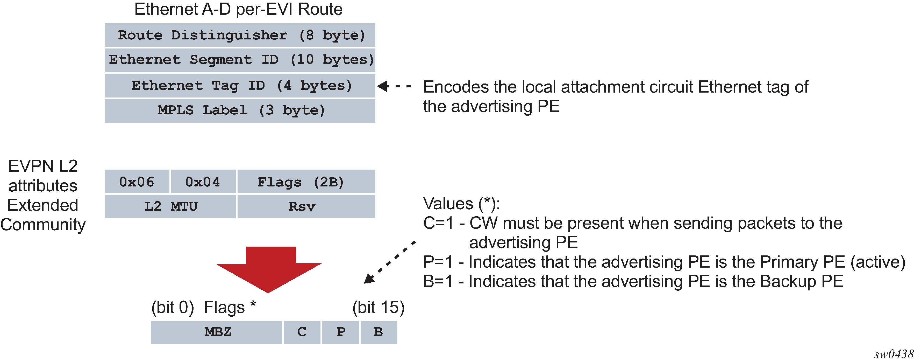
If the advertising PE has an access SAP-SDP or spoke SDP that is not part of an Ethernet Segment (ES), the PE populates the fields of the AD per-EVI route with the following values:
-
Ethernet Tag ID field is encoded with the value configured by the user in the service bgp-evpn local-attachment-circuit eth-tag value command.
-
RD and MPLS label values are encoded as specified in RFC 7432. For VXLAN, the MPLS field encodes the VXLAN VNI.
-
ESI is 0.
-
The route is sent along an EVPN L2 attributes extended community, as specified in RFC 8214, where:
-
type and subtype are 0x06 and 0x04 as allocated by IANA
-
flag C is set if a control word is configured in the service; C is always zero for VXLAN tunnels
-
P and B flags are zero
-
L2 MTU is encoded with a service MTU configured in the Epipe service
-
If the advertising PE has an access SAP-SDP or spoke SDP that is part of an ES, the AD per-EVI route is sent with the information described above, with the following minor differences:
-
The ESI encodes the corresponding non-zero value.
-
The P and B flags are set in the following cases:
-
All-active multihoming
-
All PEs that are part of the ES always set the P flag.
-
The B flag is never set in the all-active multihoming ES case.
-
-
Single-active multihoming
-
Only the DF PE sets the P bit for an EVI and the remaining PEs send it as P=0.
-
Only the backup DF PE sets the B bit.
If more than two PEs are present in the same single-active ES, the backup PE is the winner of a second DF election (excluding the DF). The remaining non-DF PEs send B=0.
-
-
Also, ES and AD per-ES routes are advertised and processed for the Ethernet-Segment, as described in RFC 7432 ESs. The ESI label sent with the AD per-ES route is used by BUM traffic on VPLS services; it is not used for Epipe traffic.
EVPN-VPWS for VXLAN tunnels in Epipe services
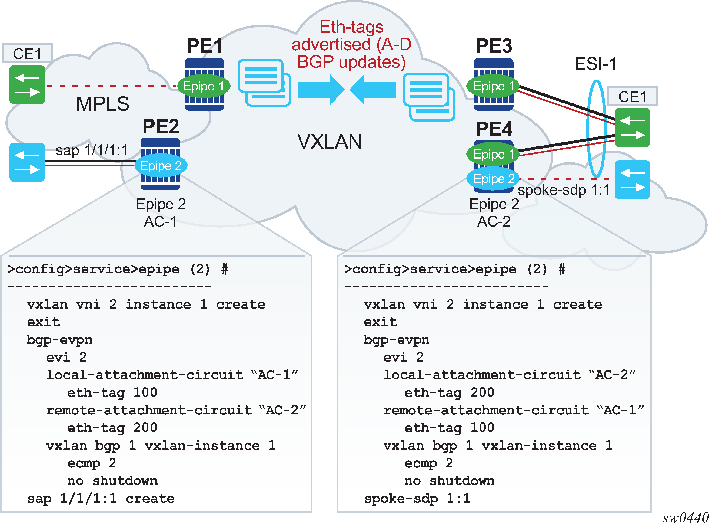
BGP-EVPN can be enabled in Epipe services with either SAPs or spoke SDPs at the access, as shown in Figure: EVPN-MPLS VPWS.
EVPN-VPWS is supported in VXLAN networks that also run EVPN-VXLAN in VPLS services. From a control plane perspective, EVPN-VPWS is a simplified point-to-point version of RFC 7432 for E-Line services for the following reasons:
-
EVPN-VPWS does not use inclusive multicast, MAC/IP routes or IP-prefix routes.
-
AD Ethernet per-EVI routes are used to advertise the local attachment circuit identifiers at each side of the VPWS instance. The attachment circuit identifiers are configured as local and remote Ethernet tags. When an AD per-EVI route is imported and the Ethernet tag matches the configured remote Ethernet tag, an EVPN destination is created for the Epipe.
In the following configuration example, Epipe 2 is an EVPN-VPWS service between PE2 and PE4 (as shown in Figure: EVPN-MPLS VPWS).
PE2>config>service>epipe(2)#
-----------------------
vxlan vni 2 instance 1 create
exit
bgp
exit
bgp-evpn
  evi 2
  local-attachment-circuit "AC-1"
    eth-tag 100
  remote-attachment-circuit "AC-2"
    eth-tag 200
  vxlan bgp 1 vxlan-instance 1
    ecmp 2
    no shutdown
sap 1/1/1:1 create
PE4>config>service>epipe(2)#
-----------------------
vxlan vni 2 instance 1 create
exit
bgp
exit
bgp-evpn
  evi 2
  local-attachment-circuit "AC-2"
    eth-tag 200
  remote-attachment-circuit "AC-1"
    eth-tag 100
  vxlan bgp 1 vxlan-instance 1
    ecmp 2
    no shutdown
spoke-sdp 1:1
The following considerations apply to the preceding example configuration:
-
When the EVI value is lower than 65535, the EVI is used to automatically derive the route-target or route-distinguisher of the service. For EVI values greater than 65535, the route-distinguisher is not automatically derived and the route-target is automatically derived, if evi-three-byte-auto-rt is configured. The EVI values must be unique in the system regardless of the type of service to which they are assigned (Epipe or VPLS).
-
Support for the following BGP-EVPN commands in Epipe services is the same as in VPLS services:
-
vxlan bgp 1 vxlan-instance 1
-
vxlan send-tunnel-encap
-
vxlan shutdown
-
vxlan ecmp
-
-
The following BGP-EVPN commands identify the local and remote attachment circuits, with the configured Ethernet tags encoded in the advertised and received AD Ethernet per-EVI routes:
-
local-attachment-circuit name
-
local-attachment-circuit name eth-tag tag-value; where tag-value is 1 to 16777215
-
remote-attachment-circuit name
-
remote-attachment-circuit name eth-tag tag-value; where tag-value is 1 to 16777215
Changes to remote Ethernet tags are allowed without shutting down BGP-EVPN VXLAN or the Epipe service. The local AC Ethernet tag value cannot be changed without BGP-EVPN VXLAN shutdown.
Both local and remote Ethernet tags are mandatory to bring up the Epipe service.
-
EVPN-VPWS Epipes can also be configured with the following characteristics:
-
Access attachment circuits can be SAPs or spoke SDP. Only manually-configured spoke SDP is supported; BGP-VPWS and endpoints are not supported. The VC switching configuration is not supported on BGP-EVPN enabled pipes.
-
EVPN-VPWS Epipes can advertise the Layer 2 (service) MTU and check its consistency as follows:
-
The advertised MTU value is taken from the configured service MTU in the Epipe service.
-
The received L2 MTU is compared to the local value. In case of a mismatch between the received MTU and the configured service MTU, the system does not set up the EVPN destination; as a result, the service does not come up.
Consider the following:
-
The system does not check the network port MTU value.
-
If the received L2 MTU value is 0, the MTU is ignored.
-
-
Using A/S PW and MC-LAG with EVPN-VPWS Epipes
The use of A/S PW (for access spoke SDP) and MC-LAG (for access SAPs) provides an alternative redundant solution for EVPN-VPWS that do not use the EVPN multi homing procedures described in RFC 8214. Figure: A/S PW and MC-LAG support on EVPN-VPWS shows the use of both mechanisms in a single Epipe.
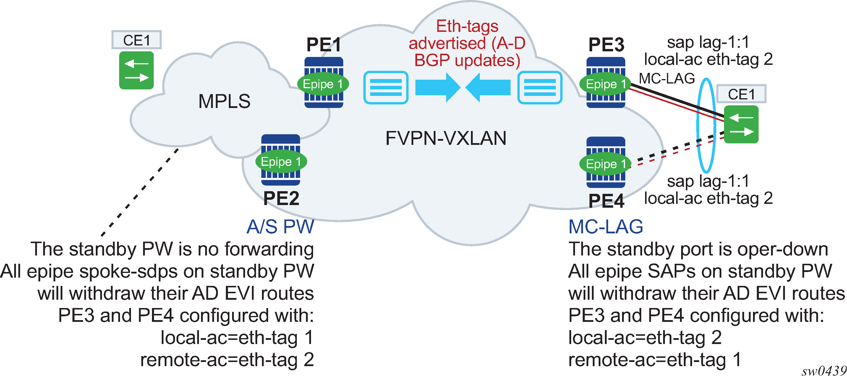
In Figure: A/S PW and MC-LAG support on EVPN-VPWS, an A/S PW connects the CE to PE1 and PE2 (left side of the diagram), and an MC-LAG connects the CE to PE3 and PE4 (right side of the diagram). As EVPN multi homing is not used, there are no AD per-ES routes or ES routes. The redundancy is handled as follows:
-
PE1 and PE2 are configured with Epipe-1, where a spoke SDP connects the service in each PE to the access CE. The local AC Ethernet tag is 1 and the remote AC Ethernet tag is 2 (in PE1/PE2).
-
PE3 and PE4 are configured with Epipe-1, where each PE has a lag SAP that belongs to a previously-configured MC-LAG construct. The local AC Ethernet tag is 2 and the remote AC Ethernet tag is 1.
-
An endpoint and A/S PW is configured on the CE on the left side of the diagram. PE1/PE2 are able to advertise Ethernet tag 1 based on the operating status or the forwarding status of the spoke SDP.
For example, if PE1 receives a standby PW status indication from the CE and the previous status was forward, it withdraws the AD EVI route for Ethernet tag 1. If PE2 receives a forward PW status indication and the previous status was standby or down, it advertises the AD EVI route for Ethernet tag 1.
-
The user can configure MC-LAG for access SAPs using the example configuration of PE3 and PE4, as shown in Figure: A/S PW and MC-LAG support on EVPN-VPWS. In this case, the MC-LAG determines which chassis is active and which is standby.
If PE4 becomes the standby chassis, the entire LAG port is brought down. As a result, the SAP goes operationally down and PE4 withdraws any previous AD EVI routes for Ethernet tag 2.
If PE3 becomes the active chassis, the LAG port becomes operationally up. As a result, the SAP and the PE3 advertise the AD per-EVI route for Ethernet tag 2.
EVPN multihoming for EVPN-VPWS services
EVPN multihoming is supported for EVPN-VPWS Epipe services with the following considerations:
-
Single-active and all-active multihoming is supported for SAPs and spoke SDP.
-
ESs can be shared between the Epipe (MPLS and VXLAN) and VPLS (MPLS) services for LAGs, ports, and SDPs.
-
A split-horizon function is not required because there is no traffic between the Designated Forwarder (DF) and the non-DF for Epipe services. As a result, the ESI label is never used, and the ethernet-segment multi-homing single-active no-esi-label and ethernet-segment source-bmac-lsb commands do not affect Epipe services.
-
The local Ethernet tag values must match on all PEs that are part of the same ES, regardless of the multi homing mode. The PEs in the ES use the AD per-EVI routes from the peer PEs to validate the PEs as DF election candidates for a specific EVI.
The DF election for Epipes that is defined in an all-active multi homing ES is not relevant because all PEs in the ES behave in the same way as follows:
-
All PEs send P=1 on the AD per-EVI routes.
-
All PEs can send upstream and downstream traffic, regardless of whether the traffic is unicast, multicast, or broadcast (all traffic is treated as unicast in the Epipe services).
Therefore, the following tools command shows N/A when all-active multihoming is configured.
*A:PE-2# tools dump service system bgp-evpn ethernet-segment "ESI-12" evi 6000 df
[03/18/2016 20:31:35] All Active VPWS - DF N/A
Aliasing is supported for traffic sent to an ES destination. If ECMP is enabled on the ingress PE, per-flow load balancing is performed to all PEs that advertise P=1. The PEs that advertise P=0, are not considered as next hops for an ES destination.
Although DF election is not relevant for Epipes in an all-active multi homing ES, it is essential for the following forwarding and backup functions in a single-active multihoming ES:
-
The PE elected as DF is the primary PE for the ES in the Epipe. The primary PE unblocks the SAP or spoke SDP for upstream and downstream traffic; the remaining PEs in the ES bring their ES SAPs or spoke SDPs operationally down.
-
The DF candidate list is built from the PEs sending ES routes for the same ES and is pruned for a specific service, depending on the availability of the AD per-ES and per-EVI routes.
-
When the SAP or spoke SDPs that are part of the ES come up, the AD per-EVI routes are sent with P=0 and B=0. The remote PEs do not start sending traffic until the DF election process is complete and the ES activation timer is expired, and the PEs advertise AD per-EVI routes with P and B bits other than zero.
-
The backup PE function is supported as defined in RFC 8214. The primary PE, backup, or none status is signaled by the PEs (part of the same single-active MH ES) in the P or B flags of the EVPN L2 attributes extended community. Figure: EVPN-VPWS single-active multihoming shows the advertisement and use of the primary, backup, or none indication by the PEs in the ES.
Figure: EVPN-VPWS single-active multihoming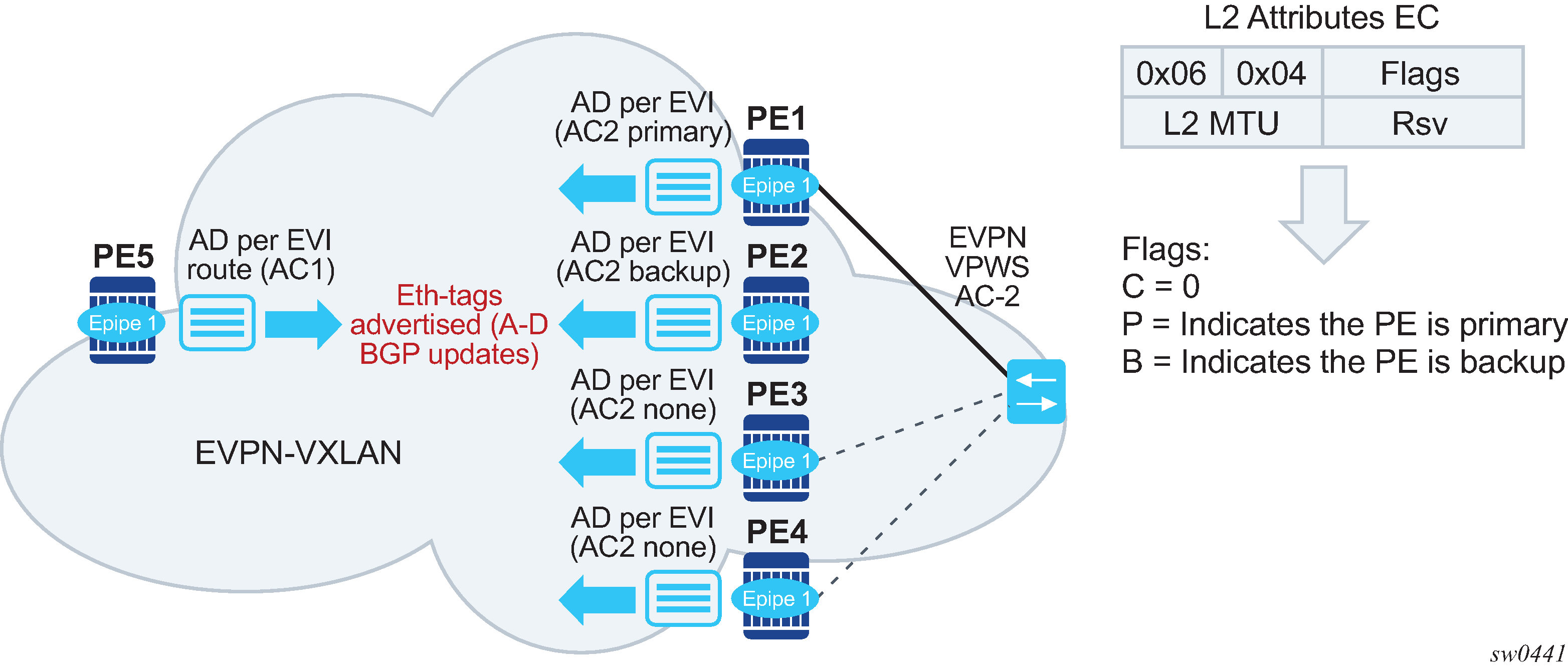
As specified in RFC 7432, the remote PEs in VPLS services have knowledge of the primary PE in the remote single-active ES, based on the advertisement of the MAC/IP routes because only the DF learns and advertises MAC/IP routes.
Because there are no MAC/IP routes in EVPN-VPWS, the remote PEs can forward the traffic based on the P/B bits. The process is described in the following list:
-
The DF PE for an EVI (PE1) sends P=1 and B=0.
-
For each ES or EVI, a second DF election is run among the PEs in the backup candidate list to elect the backup PE. The backup PE sends P=0 and B=1 (PE2).
-
All remaining multi homing PEs send P=0 and B=0 (PE3 and PE4).
-
At the remote PEs (PE5), the P and B flags are used to identify the primary and backup PEs within the ES destination. The traffic is then sent to the primary PE, provided that it is active.
-
-
When a remote PE receives the withdrawal of an Ethernet AD per-ES (or per-EVI) route from the primary PE, the remote PE immediately switches the traffic to the backup PE for the affected EVIs. The backup PE takes over immediately without waiting for the ES activation timer to bring up its SAP or spoke SDP.
-
The BGP-EVPN MPLS ECMP setting also governs the forwarding in single-active multi homing, regardless of the single-active multi homing bit in the AD per-ES route received at the remote PE (PE5).
-
PE5 always sends the traffic to the primary remote PE (the owner of the P=1 bit). In case of multiple primary PEs and ECMP>1, PE5 load balances the traffic to all primary PEs, regardless of the multi homing mode.
-
If the last primary PE withdraws its AD per-EVI or per-ES route, PE5 sends the traffic to the backup PE or PEs. In case of multiple backup PEs and ECMP>1, PE1 load balances the traffic to the backup PEs.
-
Non-system IPv4/IPv6 VXLAN termination for EVPN-VPWS services
EVPN-VPWS services support non-system IPv4/IPv6 VXLAN termination. For system configuration information, see Non-system IPv4 and IPv6 VXLAN termination in VPLS, R-VPLS, and Epipe services.
EVPN multihoming is supported when the PEs use non-system IP termination, however additional configuration steps are needed in this case:
-
The configure service system bgp-evpn eth-seg es-orig-ip ip-address command must be configured with the non-system IPv4/IPv6 address used for the EVPN-VPWS VXLAN service. As a result, this command modifies the originating-ip field in the ES routes advertised for the Ethernet Segment, and makes the system use this IP address when adding the local PE as DF candidate.
-
The configure service system bgp-evpn eth-seg route-next-hop ip-address command must be configured with the non-system IP address, too. The command changes the next-hop of the ES and AD per-ES routes to the configured address.
-
The non-system IP address (in each of the PEs in the ES) must match in these three commands for the local PE to be considered suitable for DF election:
-
es-orig-ip ip-address
-
route-next-hop ip-address
-
vxlan-src-vtep ip-address
-