The BGP signaling mechanism used to establish the pseudowires is described in the BGP VPWS standards with the following differences:
As stated in Section 3 of RFC 6624, there are two modifications of messages when compared to RFC 4761:
the Encaps Types supported in the associated extended community
the addition of a circuit status vector sub-TLV at the end of the VPWS NLRI
The control flags and VPLS preference in the associated extended community are based on IETF Draft draft-ietf-bess-vpls-multihoming-01.
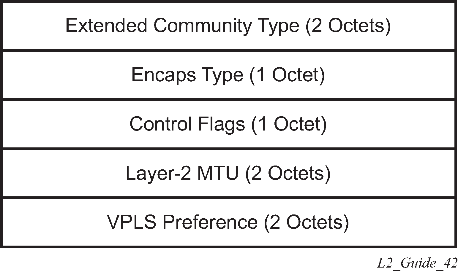
The following figure shows the format of the BGP VPWS update extended community.

extended community type
This is the value allocated by IANA for this attribute is 0x800A.
encaps type
The encapsulation type identifies the type of pseudowire encapsulation. Ethernet VLAN (4) and Ethernet Raw mode (5), as described in RFC 4448, are the only values supported. If there is a mismatch between the Encaps Type signaled and the one received, the pseudowire is created but with the operationally down state.
control flags
This is control information concerning the pseudowires, see Figure: Control flags for more information.
Layer 2 MTU
This is the MTU to be used on the pseudowires. If the received Layer 2 MTU is zero, no MTU check is performed and the related pseudowire is established. If there is a mismatch between the local service-mtu and the received Layer 2 MTU, the pseudowire is created with the operationally down state and an MTU/Parameter mismatch indication.
VPLS preference
VPLS preference has a default value of zero for BGP-VPWS updates sent by the system, indicating that it is not in use. If site-preference is configured, its value is used for the VPLS preference and is also used in the local designated forwarder election.
On receipt of a BGP VPWS update containing a non-zero value, it is used to determine to which system the pseudowire is established, as part of the VPWS update process tie-breaking rules. The BGP local preference of the BGP VPWS update sent by the system is set to the same value as the VPLS preference if the latter is non-zero, as required by the draft (as long as the D bit in the extended community is not set to 1). Consequently, attempts to change the BGP local preference when exporting a BGP VPWS update with a non-zero VPLS preference is ignored. This prevents the updates being treated as malformed by the receiver of the update.
For inter-AS, the preference information must be propagated between autonomous systems using the VPLS preference. Consequently, if the VPLS preference in a BGP-VPWS or BGP multihoming update is zero, the local preference is copied by the egress ASBR into the VPLS preference field before sending the update to the External Border Gateway Protocol (EBGP) peer. The adjacent ingress ASBR then copies the received VPLS preference into the local preference to prevent the update from being considered malformed.
The following figure shows the pseudowire control flags.

The following bits in the Control Flags are defined:
- D
- Access circuit down indicator from IETF Draft draft-kothari-l2vpn-auto-site-id-01. D is 1 if all access circuits are down, otherwise D is 0.
- A
- Automatic site ID allocation, which is not supported. This is ignored on receipt and set to 0 on sending.
- F
- MAC flush indicator. This is not supported because it relates to a VPLS service. This is set to 0 and ignored on receipt.
- C
- Presence of a control word. Control word usage is supported. When this is set to 1, packets are sent and are expected to be received, with a control word. When this is set to 0, packets are sent and are expected to be received without a control word (by default).
- S
- Sequenced delivery. Sequenced delivery is not supported. This is set to 0 on sending (no sequenced delivery) and, if a non-zero value is received (indicating sequenced delivery required), the pseudowire is not created.
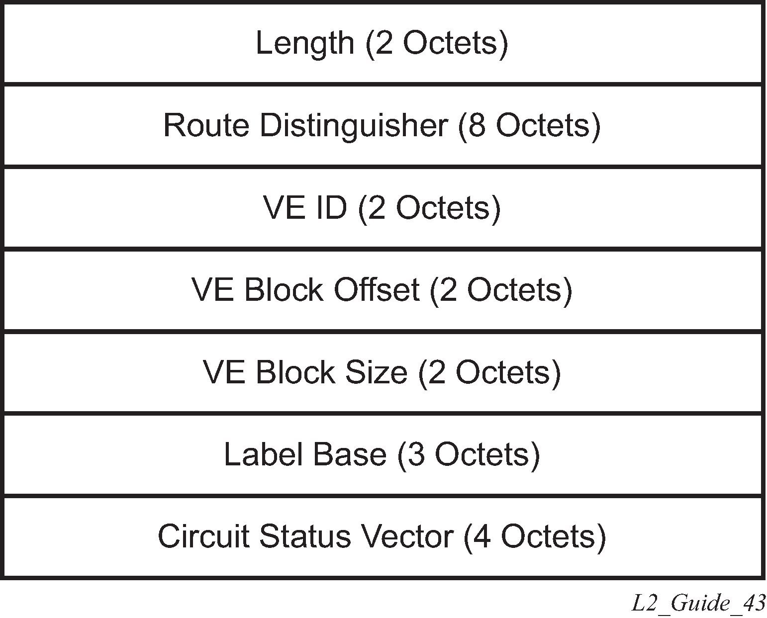
The BGP VPWS NLRI is based on that defined for BGP VPLS, but is extended with a circuit status vector as shown in the following figure.

The VE ID value is configured within each BGP VPWS service, the label base is chosen by the system, and the VE block offset corresponds to the remote VE ID because a VE block size of 1 is always used.
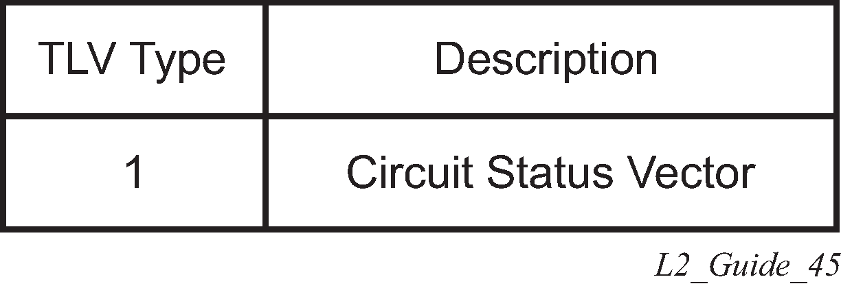
The circuit status vector is encoded as a TLV, as shown in Figure: BGP VPWS NLRI TLV extension format and Figure: Circuit status vector TLV type.


The circuit status vector is used to indicate the status of both the SAP/GRE tunnel and the status of the spoke-SDP within the local service. Because the VE block size used is 1, the most significant bit in the circuit status vector TLV value is set to 1 if either the SAP/GRE tunnel or spoke-SDP is down, otherwise it is set to 0. On receiving a circuit status vector, only the most significant byte of the CSV is examined for designated forwarder selection purposes.
If a circuit status vector length field of greater than 32 is received, the update is ignored and not reflected to BGP neighbors. If the length field is greater than 800, a notification message is sent and the BGP session restarts. Also, BGP VPWS services support a single access circuit, so only the most significant bit of the CSV is examined on receipt.
A pseudowire is established when a BGP VPWS update is received that matches the service configuration, specifically the configured route targets and remote VE ID. If multiple matching updates are received, the system to which the pseudowire is established is determined by the tie-breaking rules, as described in IETF Draft draft-ietf-bess-vpls-multihoming-01.
Traffic is sent on the active pseudowire connected to the remote designated forwarder. Traffic can be received on either the active or standby pseudowire, although no traffic should be received on the standby pseudowire because the SAP/GRE tunnel on the non-designated forwarder should be blocked.
The adv-service-mtu command can be used to override the MTU value used in BGP signaling to the far-end of the pseudowire. This value is also used to validate the value signaled by the far-end PE unless ignore-l2vpn-mtu-mismatch is also configured.
If the ignore-l2vpn-mtu-mismatch command is configured, the router does not check the value of the "Layer 2 MTU" in the "Layer2 Info Extended Community" received in a BGP update message against the local service MTU, or against the MTU value signaled by this router. The router brings up the BGP-VPWS service regardless of any MTU mismatch.