The pseudowire is set up using the following NLRI fields:
VE Block offset (VBO)
This is used to define each VE-ID set for which the NLRI is targeted.
VBO = n*VBS+1; for VBS = 8, this results in 1, 9, 17, 25, …
Targeted Remote VE-IDs are from VBO to (VBO + VBS - 1)
-
VE Block size (VBS)
Defines how many contiguous pseudowire labels are reserved, starting with the Label Base; Nokia implementation always uses a value of eight (8).
Label Base (LB)
This is the local allocated label base. The next eight consecutive labels available are allocated for remote PEs.
This BGP update is telling the other PEs that accept the RT: reach me (VE-ID = x), use a pseudowire label of LB + VE-ID – VBO using the BGP NLRI for which VBO =< local VE-ID < VBO + VBS.
Following is an example of how this algorithm works, assuming PE1 has VE-ID 7 configured:
-
PE1 allocates a label block of eight consecutive labels available, starting with LB = 1000.
-
PE1 starts sending a BGP update with pseudowire information of VBO = 1, VBS = 8, LB = 1000 in the NLRI.
-
This pseudowire information is accepted by all participating PEs with VE-IDs from 1 to 8.
-
Each of the receiving PEs uses the pseudowire label = LB + VE-ID - VBO to send traffic back to the originator PE. For example, VE-ID 2 uses pseudowire label 1001.
Assuming that VE-ID = 10 is configured in another PE4, the following procedure applies:
-
PE4 sends a BGP update with the new VE-ID in the network that is received by all the other participating PEs, including PE1.
-
Upon reception, PE1 generates another label block of 8 labels for the VBO = 9. For example, the initial PE creates new pseudowire signaling information of VBO = 9, VBS = 8, LB = 3000, and insert it in a new NLRI and BGP update that is sent in the network.
-
This new NLRI is used by the VE-IDs from 9 to 16 to establish pseudowires back to the originator PE1. For example, PE4 with VE-ID 10 uses pseudowire label 3001 to send VPLS traffic back to PE1.
-
The PEs owning the set of VE-IDs from 1 to 8 ignore this NLRI.
In addition to the pseudowire label information, the "Layer2 Info Extended Community" attribute must be included in the BGP update for BGP VPLS to signal the attributes of all the pseudowires that converge toward the originator VPLS PE.
The format is as follows:
+------------------------------------+
| Extended community type (2 octets) |
+------------------------------------+
|  Encaps Type (1 octet)             |
+------------------------------------+
|  Control Flags (1 octet)           |
+------------------------------------+
|  Layer-2 MTU (2 octet)             |
+------------------------------------+
|  Reserved (2 octets)               |
+------------------------------------+
The meaning of the fields are as follows:
extended community type
This is the value allocated by IANA for this attribute is 0x800A.
encaps type
Encapsulation type identifies the type of pseudowire encapsulation. The only value used by BGP VPLS is 19 (13 in HEX). This value identifies the encapsulation to be used for pseudowire instantiated through BGP signaling, which is the same as the one used for Ethernet pseudowire type in regular VPLS. There is no support for an equivalent Ethernet VLAN pseudowire in BGP VPLS in BGP signaling.
control flags
This field is control information concerning the pseudowires (see Figure: BGP VPLS solution).
Layer 2 MTU
This is the Maximum Transmission Unit to be used on the pseudowires
reserved
This field is reserved and must be set to zero and ignored on reception except where it is used for VPLS preference.
For inter-AS, the preference information must be propagated between autonomous systems. Consequently, as the VPLS preference in a BGP-VPLS or BGP multihoming update extended community is zero, the local preference is copied by the egress ASBR into the VPLS preference field before sending the update to the EBGP peer. The adjacent ingress ASBR then copies the received VPLS preference into the local preference to prevent the update being considered malformed.
Figure: Control flag bit vector format shows the detailed format for the control flags bit vector.
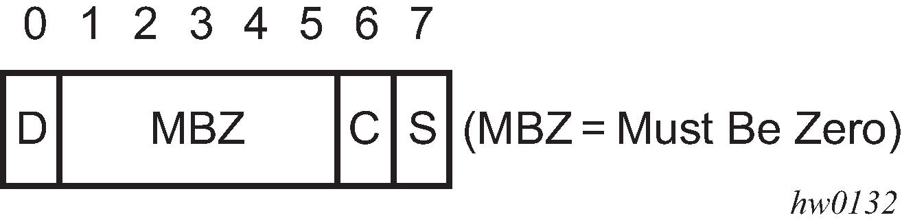
The following bits in the control flags are defined as follows:
- S
- sequenced delivery of frames that must or must not be used when sending VPLS packets to this PE, depending on whether S is 1 or 0, respectively
- C
- a Control word that must or must not be present when sending VPLS packets to this PE, depending on whether C is 1 or 0, respectively. By default, Nokia implementation uses value 0
- MBZ
- Must Be Zero bits, set to zero when sending and ignored when receiving
- D
- indicates the status of the whole VPLS instance (VSI); D = 0 if Admin and Operational status are up, D = 1 otherwise
Following are the events that set the D-bit to 1 to indicate VSI down status in the BGP update message sent out from a PE:
Local VSI is shut down administratively using the config service vpls shutdown command.
All the related endpoints (SAPs or LDP pseudowires) are down.
There are no related endpoints (SAPs or LDP pseudowires) configured yet in the VSI.
The intent is to save the core bandwidth by not establishing the BGP pseudowires to an empty VSI.
Upon reception of a BGP update message with D-bit set to 1, all the receiving VPLS PEs must mark related pseudowires as down.
The following events do not set the D-bit to 1:
The local VSI is deleted; a BGP update with UNREACH-NLRI is sent out. Upon reception, all remote VPLS PEs must remove the related pseudowires and BGP routes.
If the local SDP goes down, only the BGP pseudowires mapped to that SDP go down. There is no BGP update sent.
The adv-service-mtu command can be used to override the MTU value used in BGP signaling to the far-end of the pseudowire. This value is also used to validate the value signaled by the far-end PE unless ignore-l2vpn-mtu-mismatch is also configured.
If the ignore-l2vpn-mtu-mismatch command is configured, the router does not check the value of the "Layer 2 MTU" in the "Layer2 Info Extended Community" received in a BGP update message against the local service MTU, or against the MTU value signaled by this router. The router brings up the BGP-VPLS service regardless of any MTU mismatch.