This section describes the implementation and configuration of redundant Mirror/Lawful Intercept services using redundant pseudowires.
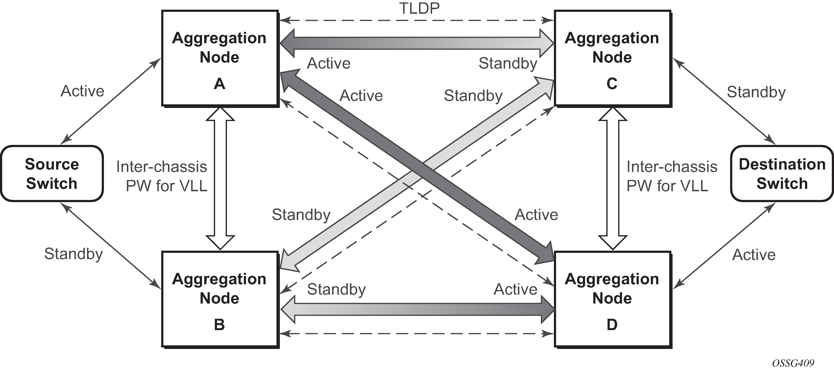
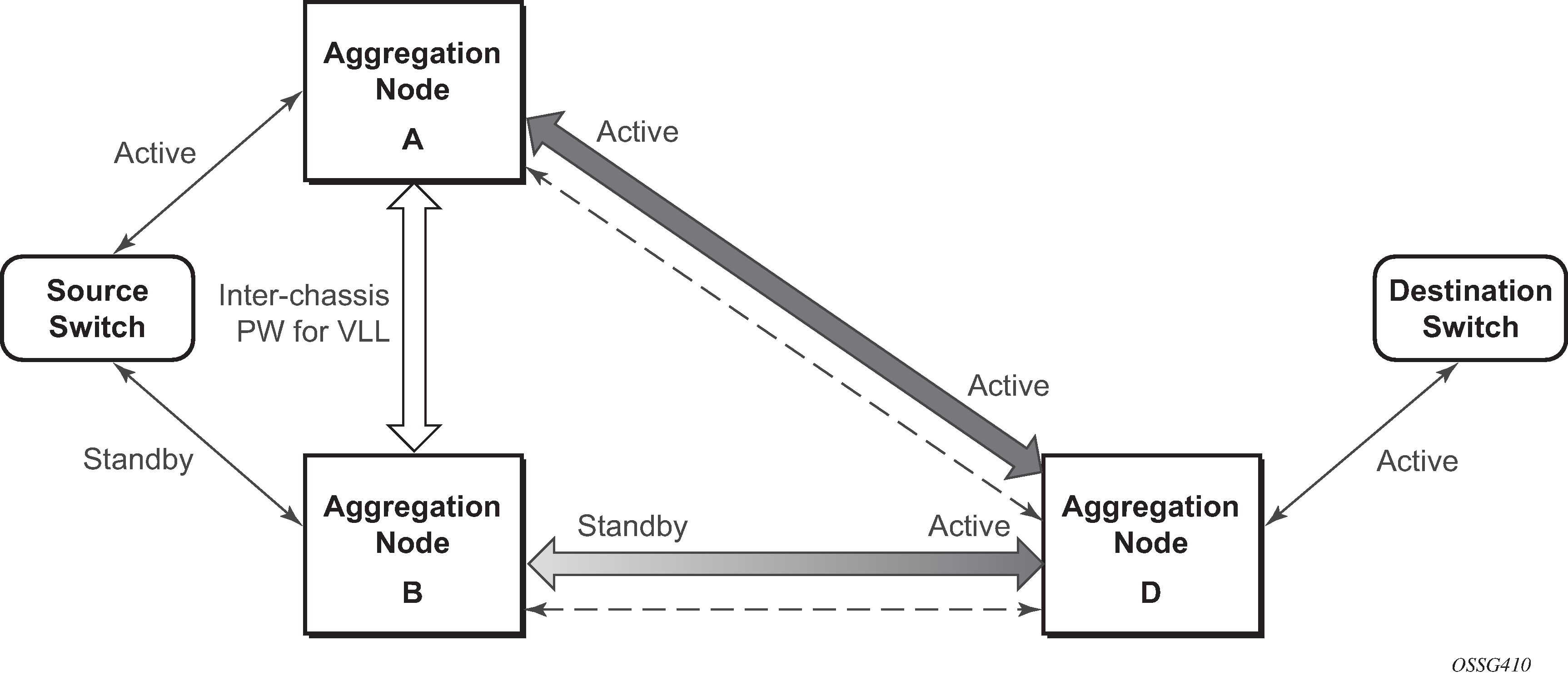
Regardless of the protection mechanism (MC-LAG, STP, or APS) the source switch only transmits on the active link and not simultaneously on the standby link. As a result, when configuring a redundant mirror or LI service or a mirror service where the customer has a redundant service but the mirror or LI service is not redundant the mirror source must be configured on both (A and B) PE nodes. In either case, the PE with a mirror source establishes a pseudowire to each eligible PE where the mirror / LI service terminates.

It is important to note that to provide protection if the active SDP between node A and D fails and the need to limit the number of lost data for LI the ICB between node A and B must be supported. As a result, when the SDP connecting nodes A and D fails the data on its way from the source switch to node A and the data in node A must be directed by the ICB to node B and from there to node D.
This functionality is already supported in when providing pseudo wire redundancy for VLLs and must be extended to mirror or LI service redundancy.

The notable difference with scenarios standard pseudo wire redundancy scenarios is that provided the customer service is redundant on nodes A and B (Figure: State engine for redundant service to a redundant mirror service and Figure: State engine for redundant service to a non-redundant mirror service) both aggregation node A and Aggregation node B maintain an active Pseudo wire to Node D who in turn has an active link to the destination switch. If in Figure: State engine for redundant service to a redundant mirror service, the link between D and the destination switch is disconnected, then both aggregation A and B must switch to use pseudowire connection to Node C.

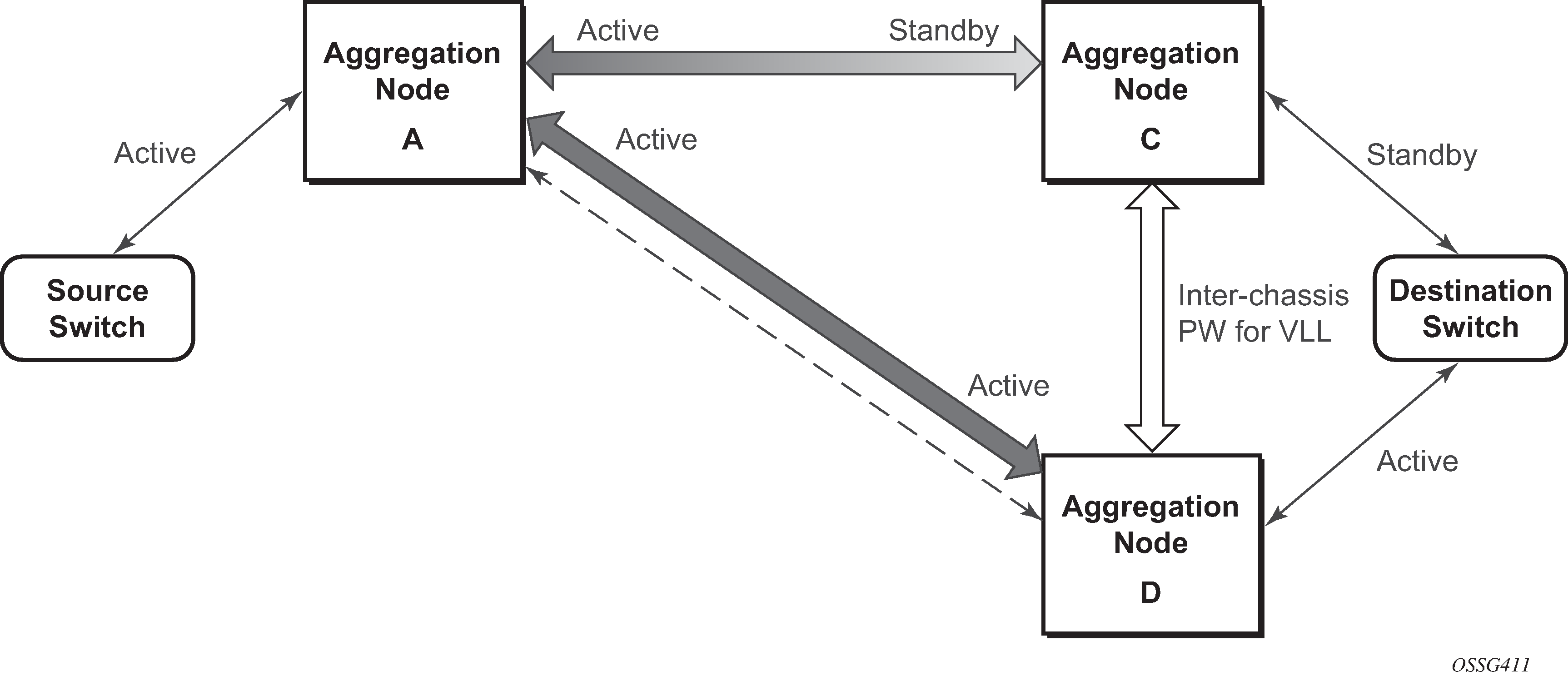
In the case where a non-redundant service is being mirrored to a redundant mirror service (Figure: State engine for a non-redundant service to a redundant mirror service ) the source aggregation node (A) can only maintain a pseudo wire to the active destination aggregation node (D). Should the link between aggregation node D and the destination switch fail then the pseudo wire must switch to the new active aggregation node (C).