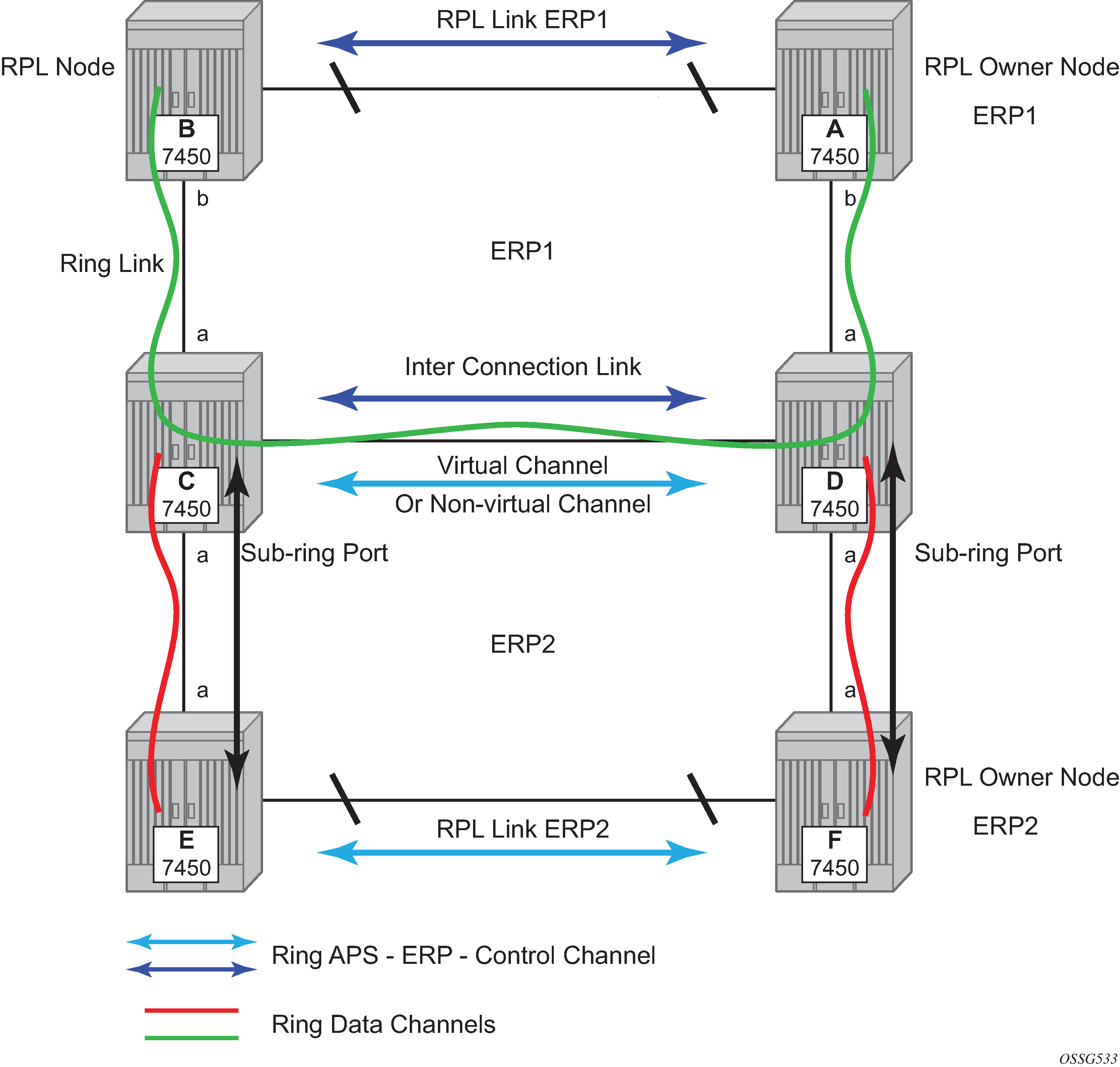
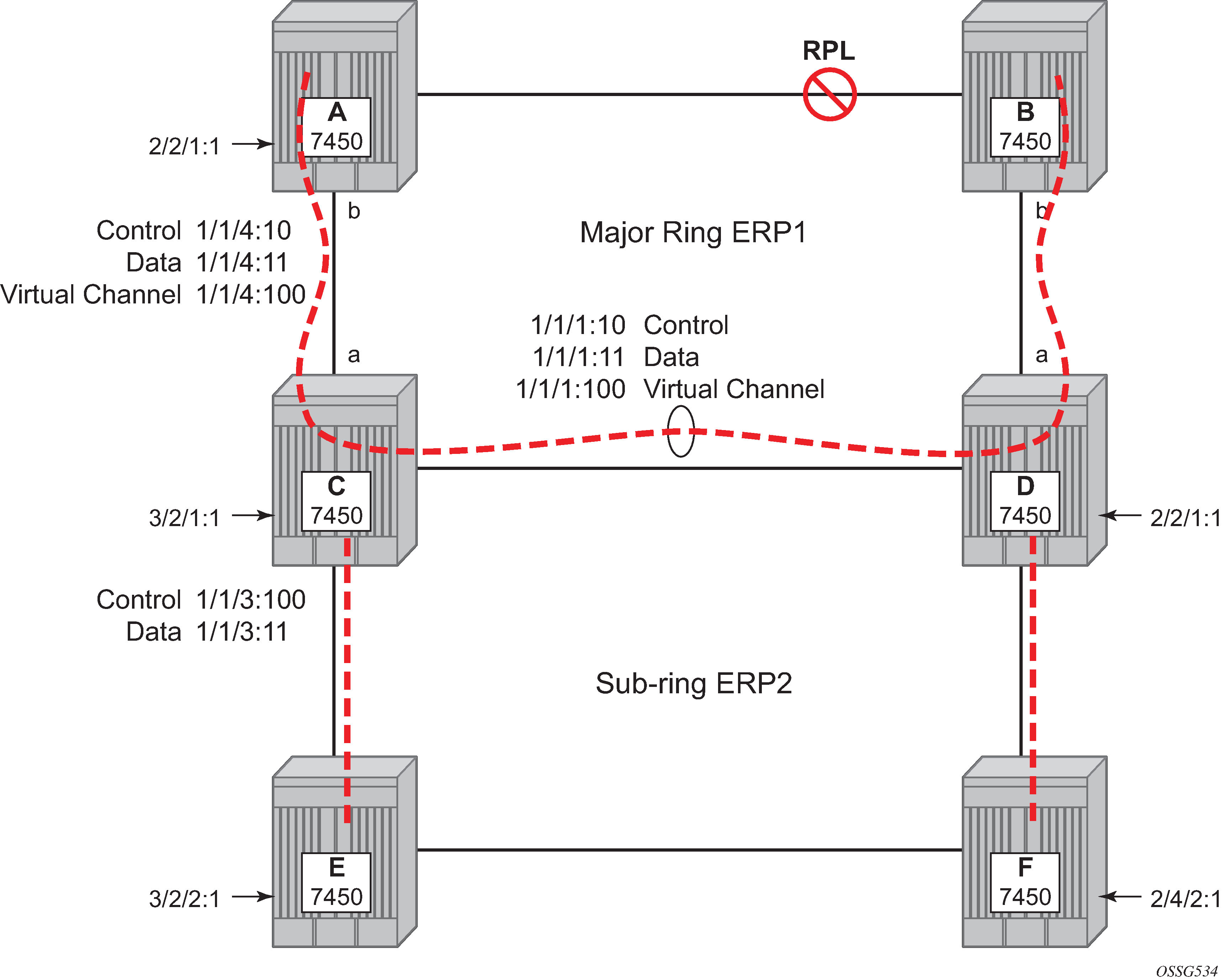
The 7450 ESS, 7750 SR, and 7950 XRS support both the virtual channel and non-virtual channel for sub-ring control communication. In the virtual channel mode, a dedicated VID, other than the major ring RAPs control channel is configured as a data instance on the major ring. This allows the sub-ring control messages and state machine logic to behave similar to a major ring. In the non-virtual channel mode, the sub-ring is only connected by the RAPs control channels on the sub-ring itself. This mode offers slightly less redundancy in the RAPs messaging than the virtual channel mode because sub-ring RAPs messages are not propagated across the major ring. When non-virtual link is configured, the protocol allows RPL messages over the sub-ring blocked link.

Sub-ring configuration is similar to major ring configuration and consists of three parts: Ethernet-ring instance configuration, control VPLS configuration, and data VPLS configuration (data instance or data channel). The Ethernet-ring configuration of a sub-ring is tied to a major ring and only one path is allowed.
As with a major ring, the forwarding of CCMs and G.8032 R-APS messages continues in the control VPLS even if the service or its SAPs are administratively shut down. The Ethernet ring instance can be shut down if it is needed to stop the operation of the ring on a node.
The data VPLS can be configured on the major ring, and in the example, shares the same VID (SAP encapsulation) on both the major ring and the sub-ring to keep data on the same VLAN ID everywhere.
The following illustrates an example sub-ring configuration on Node C:
eth-ring 2
        description "Ethernet Sub Ring on Ring 1"
        sub-ring virtual-link // Using a virtual link
            interconnect ring-id 1 // Link to Major Ring 1
                propagate-topology-change
            exit
        exit
        path a 1/1/3 raps-tag 100 // Ring control uses VID 100
            eth-cfm
                mep 9 domain 1 association 4
                    ccm-enable
                    control-mep
                    no shutdown
                exit
            exit
            no shutdown
        exit
        no shutdown
    exit
If the sub-ring had been configured as a non-virtual-link, the sub-ring configuration above and on all the other sub-ring nodes for this sub-ring would become:
        sub-ring non-virtual-link // Not using a virtual link

# Control Channel for the Major Ring ERP1 illustrates that Major ring
# control is still separate from Sub-ring control
  vpls 10 customer 1 create
      description "Control VID 10 for Ring 1 Major Ring"
      stp shutdown
      sap 1/1/1:10 eth-ring 1 create
          stp shutdown
          exit
      sap 1/1/4:10 eth-ring 1 create
          stp shutdown
          exit
      no shutdown
  exit

# Data configuration for the Sub-Ring

  vpls 11 customer 1 create
      description "Data on VID 11 for Ring 1"
      stp shutdown
      sap 1/1/1:11 eth-ring 1 create // VID 11 used for ring
          stp shutdown
      exit
      sap 1/1/4:11 eth-ring 1 create
          stp shutdown
      exit
      sap 1/1/3:11 eth-ring 2 create // Sub-ring data
          stp shutdown
      exit
      sap 3/2/1:1 create
      description "Local Data SAP"
          stp shutdown
      no shutdown
  exit

# Control Channel for the Sub-Ring using a virtual link. This is
# a data channel as far as Ring 1 configuration. Other Ring 1
# nodes also need this VID to be configured.

  vpls 100 customer 1 create
      description "Control VID 100 for Ring 2 Interconnection"
      split-horizon-group "s1" create //Ring Split horizon Group
      exit
      stp shutdown
      sap 1/1/1:100 split-horizon-group "s1" eth-ring 1 create
          stp shutdown
      exit
      sap 1/1/4:100 split-horizon-group "s1" eth-ring 1 create
          stp shutdown
      exit
      sap 1/1/3:100 eth-ring 2 create
          stp shutdown
      exit
      no shutdown
  exit
If the sub-ring had been configured as a non-virtual-link, the configuration above would then become:
  vpls 100 customer 1 create
      description "Control VID 100 for Ring 2 Interconnection"
      sap 1/1/3:100 eth-ring 2 create
          stp shutdown
      exit
      no shutdown
  exit
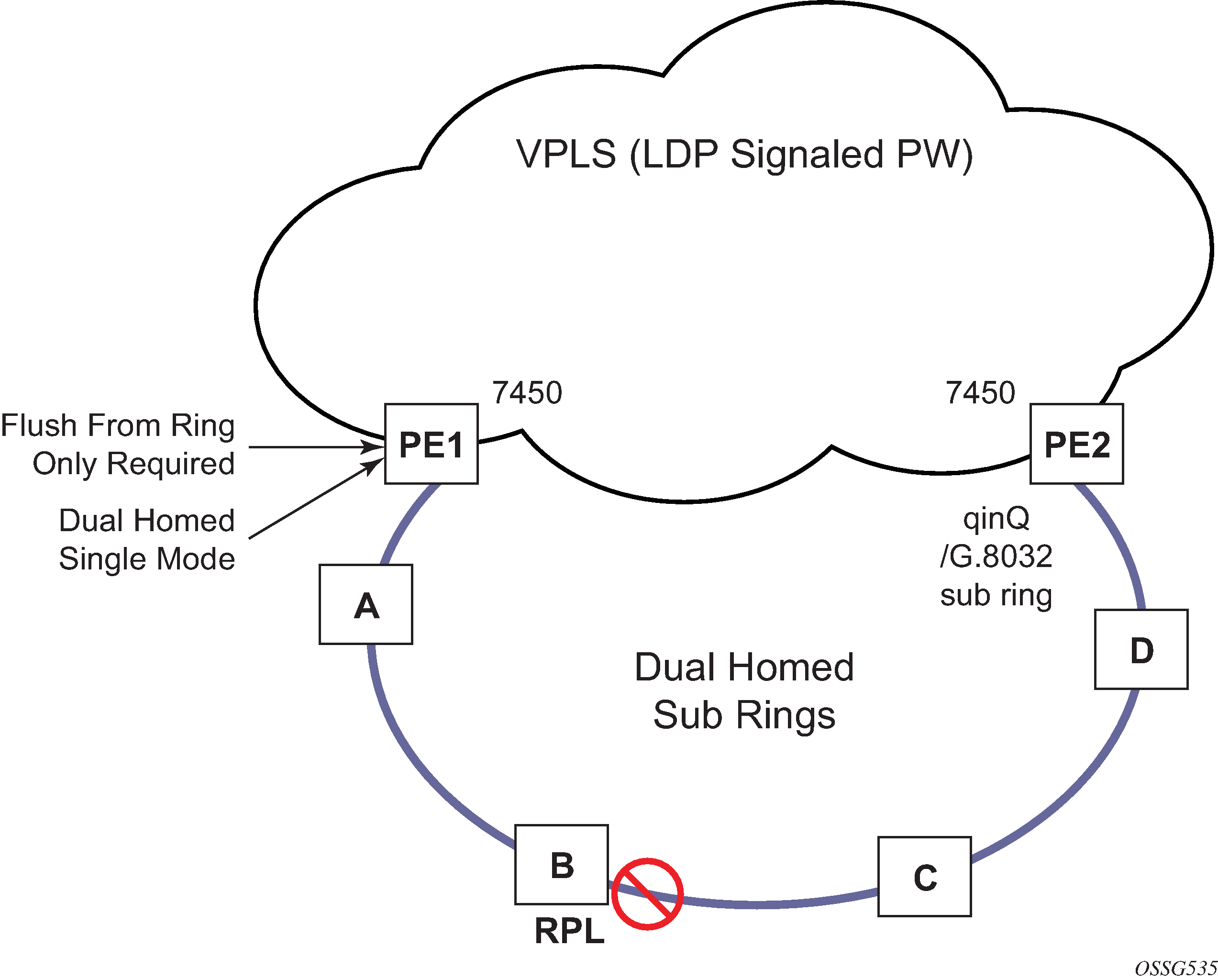
The 7450 ESS, 7750 SR, and 7950 XRS allow for a special configuration of the non-virtual link sub-ring that can be homed to a VPLS service illustrated in Figure: 0-6 sub-ring homed to VPLS. This is an economical way to have a redundant ring connection to a VPLS service. This is currently supported only for dot1Q and QinQ sub-rings and only on LDP based VPLS. The primary application for this is access rings that require resiliency. This configuration shows the configuration for a sub-ring at an interconnection node without a virtual channel and interconnected to a VPLS. A VPLS service 1 is used to terminate the ring control. The Ethernet ring data SAP appears in the associated LDP based VPLS service 5.

The following is an example sub-ring configuration for VPLS (at PE1):
eth-ring 1
      description "Ethernet Ring 1"
      guard-time 20
      no revert-time
      rpl-node nbr
      sub-ring non-virtual-link
          interconnect vpls // VPLS is interconnection type
              propagate-topology-change
          exit
      exit
      path a 1/1/3 raps-tag 1.1
          description "Ethernet Ring : 1 Path on LAG"
          eth-cfm
          mep 8 domain 1 association 8
               ccm-enable
               control-mep
               no shutdown
            exit
        exit
        no shutdown
    exit
    no shutdown
exit

# Configuration for the ring control interconnection termination:
  vpls 1 customer 1 create
      description "Ring 1 Control termination"
      stp shutdown
      sap 1/1/3:1.1 eth-ring 1 create //path a control
          stp shutdown
      exit
      no shutdown
  exit

# Configuration for the ring data into the LDP based VPLS Service

  vpls 5 customer 1 create
      description "VPLS Service at PE1"
      stp
          no shutdown
      exit
      sap 1/1/3:2.2 eth-ring 1 create
          stp shutdown
      exit
      sap 1/1/5:1 create
      exit
      mesh-sdp 5001:5 create //sample LDP MPLS LSPs
      exit
      mesh-sdp 5005:5 create
      exit
      mesh-sdp 5006:5 create
      exit

      no shutdown
  exit
Ethernet-rings and sub-rings offer a way to build a scalable resilient Ethernet transport network. Figure: 0-7 multi ring hierarchy illustrates a hierarchical ring network using PBB where dual homed services are connected to a PBB based Ethernet ring network.

The major rings are connected by sub-rings to the top level major ring. These sub-rings require virtual channel and do not work with non-virtual channel. Ring flushing is contained to major rings, or in the case of a sub-ring link or node failure, to the sub-ring and the directly attached major rings.