The timing subsystem for the platforms has a central clock located on the CPM (motherboard). The timing subsystem performs many of the duties of the network element clock as defined by Telcordia (GR-1244-CORE) and ITU-T G.781.
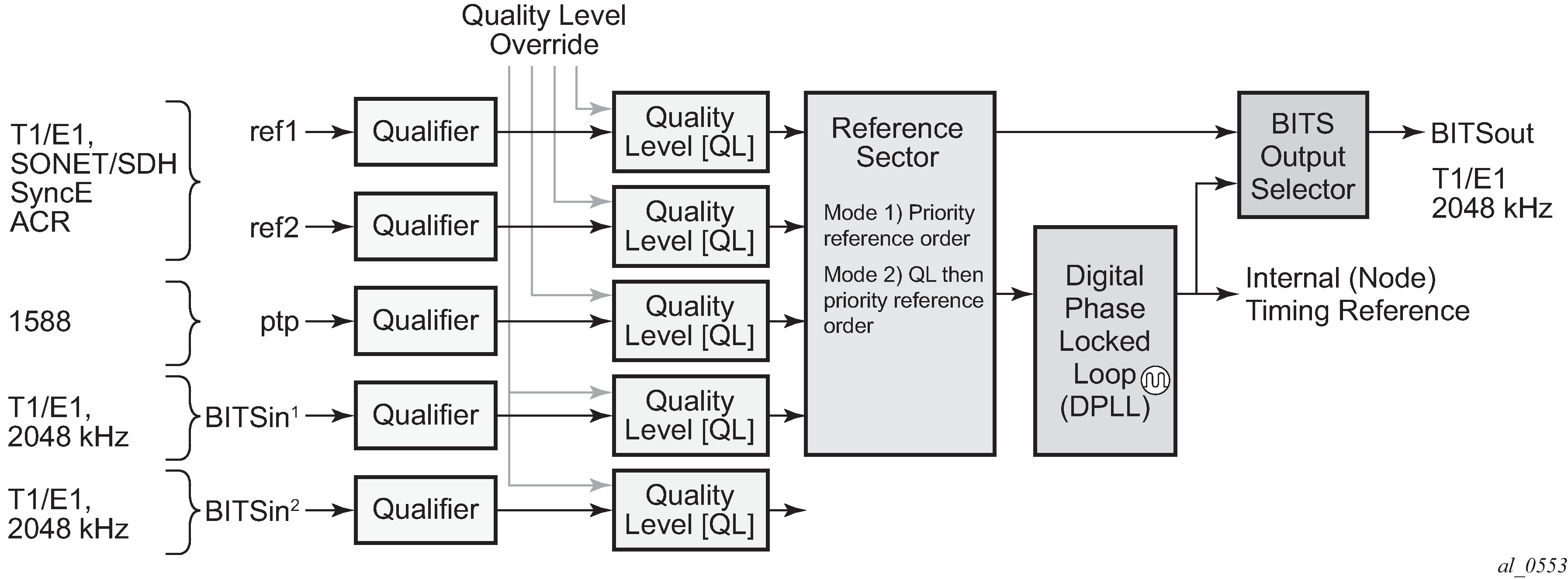
The system can select from up to three (7950 XRS) or four (7450 ESS and 7750 SR) timing inputs to train the local oscillator. The priority order of these references must be specified. This is a simple ordered list of inputs: {bits, ref1, ref2, ptp}. The CPM clock output shall have the ability to drive the clocking for all line cards in the system. The routers support selection of the node reference using Quality Level (QL) indications. See Figure: CPM clock synchronization reference selection for a description of the synchronization selection process for the CPM clock.
The recovered clock can derive its timing from any of the following:
OC3/STM1, OC12/STM4, OC48/STM16, OC192/STM64 ports (7450 ESS and 7750 SR only)
T1/E1 CES channel (adaptive clocking) (7750 SR only)
Synchronous Ethernet ports
T1/E1 port (7750 SR only)
BITS port on the CPM or CCM module
10GE ports in WAN PHY mode
IEEE 1588v2 timeReceiver port (PTP) (7450 ESS and 7750 SR only)
SyncE/1588 port on the CPM or the CCM
The BITS ports accept T1 or E1 signal formats. Some hardware also supports the 2048 kHz signal format. The format must be common between all BITSin and BITSout ports.
All settings of the signal characteristics for the BITS input apply to both ports. When the active CPM considers the BITS input as a possible reference, it first considers the BITS input port on the active CPM or CCM followed by the BITS input port on the standby CPM or CCM in that relative priority order. This relative priority order is in addition to the user-definable ref-order. For example, a ref-order of bits ref1 ref2 would actually be BITS in (active CPM or CCM), followed by BITS in (standby CPM or CCM), followed by ref1, followed by ref2. When ql-selection is enabled, the QL of each BITS input port is viewed independently. The higher QL source is chosen.
When the active CPM considers the SyncE/1588 as a possible reference, the active CPM first considers the SyncE/1588 port on the active CPM or CCM, followed by the SyncE/1588 port on the standby CPM or CCM in that relative priority order. This relative priority order is in addition to the user-definable ref-order. For example, a ref-order of synce ref1 ref2 would actually be SyncE/1588 (active CPM or CCM), followed by SyncE/1588 (standby CPM or CCM), followed by ref1, followed by ref2. When ql-selection is enabled, the QL of each SyncE/1588 input port is viewed independently. The higher QL source is chosen.
The following behavior applies to the platform architecture existing on 7750 SR-7/12/12e, 7750 SR-2s/7s/14s, 7750 SR-1e/2e/3e, 7750 SR-a4/a8, and 7450 ESS-7/12. When the BITS or SyncE port on the standby CPM is an option as input reference into the central clock of the active CPM, a display of the central clock data on the standby CPM indicates that it is locked to its local BITS or SyncE input. This is expected behavior and required to make the BITS input on the standby available to the active CPM as an option for reference selection.
The restrictions on the location for the source-port or source-bits for ref1 and ref2 are listed in Table: Ref1 and ref2 timing references.
| Platform | Ref1 slots | Ref2 slots | Notes |
|---|---|---|---|
7450 ESS-7 |
1 to 2 |
3 to 5 |
— |
7450 ESS-12 |
1 to 5 |
6 to 10 |
— |
7750 SR-1 |
1 |
1 |
Ref1 and ref2 cannot be on the same MDA |
7750 SR-7 |
1 to 2 |
3 to 5 |
— |
7750 SR-12 |
1 to 5 |
6 to 10 |
— |
7750 SR-12e |
1 to 5 |
6 to 9 |
— |
7750 SR-a4 |
1 |
1 |
Ref1 and ref2 cannot be on the same MDA. Two CPMs must be installed to allow two references to be used. |
7750 SR-a8 |
1 to 2 |
1 to 2 |
Ref1 and ref2 cannot be on the same slot. |
7750 SR-1e |
1 |
1 |
Ref1 and ref2 cannot be on the same MDA |
7750 SR-2e |
1 to 2 |
1 to 2 |
Ref1 and ref2 cannot be on the same MDA |
7750 SR-3e |
1 to 3 |
1 to 3 |
Ref1 and ref2 cannot be on the same MDA |
7750 SR-1s |
1 |
1 |
Ref1 and ref2 cannot be on the same MAC chip. See the 7750 SR-1s Installation Guide or use the show datapath command for the mappings. |
7750 SR-2s |
1 to 2 |
1 to 2 |
Ref1 and ref2 cannot be on the same slot. |
7750 SR-7s |
1 to 6 |
1 to 6 |
Ref1 and ref2 cannot be on the same slot. Slot 6 cannot be used if a CPM has been installed in that slot. |
7750 SR-14s |
1 to 6 |
1 to 6 |
Ref1 and ref2 cannot be on the same slot. |
7950 XRS-20 |
1 to 10 |
1 to 10 |
Ref1 and ref2 cannot be on the same slot |
7950 XRS-20e |
1 to 10 |
1 to 10 |
Ref1 and ref2 cannot be on the same slot |
7950 XRS-40 |
1 to 10 |
1 to 10 |
Ref1 and ref2 cannot be on the same slot |
The BITS output ports can be configured to provided either the unfiltered recovered line clock from a line card port or the output of the central clock. The first case would be used if the port was connected to deliver an input reference directly to dedicated timing device in the facility (BITS or SASE device). The second case would be used to test the quality of the clocking used by the router.
When QL selection mode is disabled, then the reversion setting controls when the central clock can re-select a previously failed reference.
Table: Revertive, non-revertive timing reference switching operation shows the selection followed for two reference in both revertive and non-revertive modes:
| Status of reference A | Status of reference B | Active reference non-revertive case | Active reference revertive case |
|---|---|---|---|
OK |
OK |
A |
A |
Failed |
OK |
B |
B |
OK |
OK |
B |
A |
OK |
Failed |
A |
A |
OK |
OK |
A |
A |
Failed |
Failed |
holdover |
holdover |
OK |
Failed |
A |
A |
Failed |
Failed |
holdover |
holdover |
Failed |
OK |
B |
B |
Failed |
Failed |
holdover |
holdover |
OK |
OK |
A or B |
A |