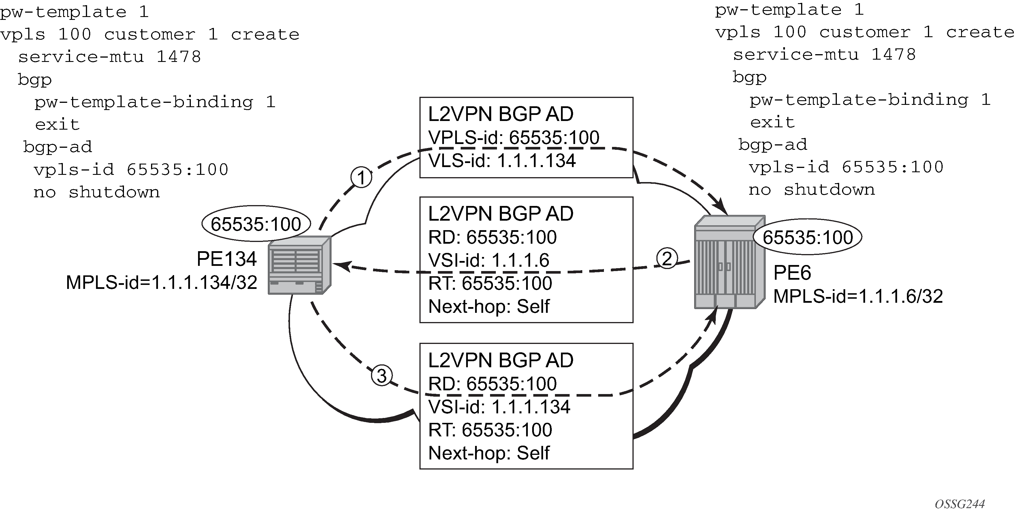
Using Figure: BGP AD configuration example, assume PE6 was previously configured with VPLS 100 as indicated by the configurations code in the upper right. The BGP AD process commences after PE134 is configured with the VPLS 100 instance, as shown in the upper left. This shows a basic BGP AD configuration. The minimum requirement for enabling BGP AD on a VPLS instance is configuring the VPLS-ID and pointing to a pseudowire template.

In many cases, VPLS connectivity is based on a pseudowire mesh. To reduce the configuration requirement, the BGP values can be automatically generated using the VPLS-ID and the MPLS router-ID. By default, the lower six bytes of the VPLS-ID are used to generate the RD and the RT values. The VSI-ID value is generated from the MPLS router-ID. All of these parameters are configurable and can be coded to suit requirements and build different topologies.
PE134>config>service>vpls>bgp-ad#
[no] shutdown - Administratively enable/disable BGP auto-discovery
vpls-id - Configure VPLS-ID
vsi-id + Configure VSI-id
The show service command shows the service information, the BGP parameters, and the SDP bindings in use. When the discovery process is completed successfully, each endpoint has an entry for the service.
PE134># show service l2-route-table
=======================================================================
Services: L2 Route Information - Summary Service
=======================================================================
Svc Id     L2-Routes (RD-Prefix)                 Next Hop        Origin
               Sdp Bind Id
-----------------------------------------------------------------------
100        65535:100-1.1.1.6                     1.1.1.6         BGP-L2
               17406:4294967295
-----------------------------------------------------------------------
No. of L2 Route Entries: 1
=======================================================================
PERs6>#

PERs6># show service l2-route-table
=======================================================================
Services: L2 Route Information - Summary Service
=======================================================================
Svc Id     L2-Routes (RD-Prefix)                 Next Hop        Origin
               Sdp Bind Id
-----------------------------------------------------------------------
100        65535:100-1.1.1.134                   1.1.1.134       BGP-L2
               17406:4294967295
-----------------------------------------------------------------------
No. of L2 Route Entries: 1
=======================================================================
PERs6>#
When only one of the endpoints has an entry for the service in the l2-routing-table, it is most likely a problem with the RT values used for import and export. This would most likely happen when different import and export RT values are configured using a router policy or the route-target command.
Service-specific commands continue to be available to show service-specific information, including status:
PERs6# show service sdp-using
===============================================================================
SDP Using
===============================================================================
SvcId       SdpId               Type    Far End        Opr S* I.Label  E.Label
-------------------------------------------------------------------------------
100         17406:4294967295    BgpAd   10.1.1.134      Up     131063   131067
-------------------------------------------------------------------------------
Number of SDPs : 1
===============================================================================
* indicates that the corresponding row element may have been truncated.
BGP AD advertises the VPLS-ID in the extended community attribute, VSI-ID in the NLRI, and the local PE ID in the BGP next hop. At the receiving PE, the VPLS-ID is compared against locally provisioned information to determine whether the two PEs share a common VPLS. If they do, the BGP information is used in the signaling phase (see Configuring BGP VPLS).