PW payload delivery from the I/O ports to the FPE based PW-port (and SAP) is facilitated via an internal cross-connect which is built on top of PXC sub-ports. Such cross-connect allows for mapping between PWs and PW-ports even in cases where PW payloads have overlapping VLANS. This concept is shown in Figure: Multiplexing PWs over PXC-based internal cross-connect .
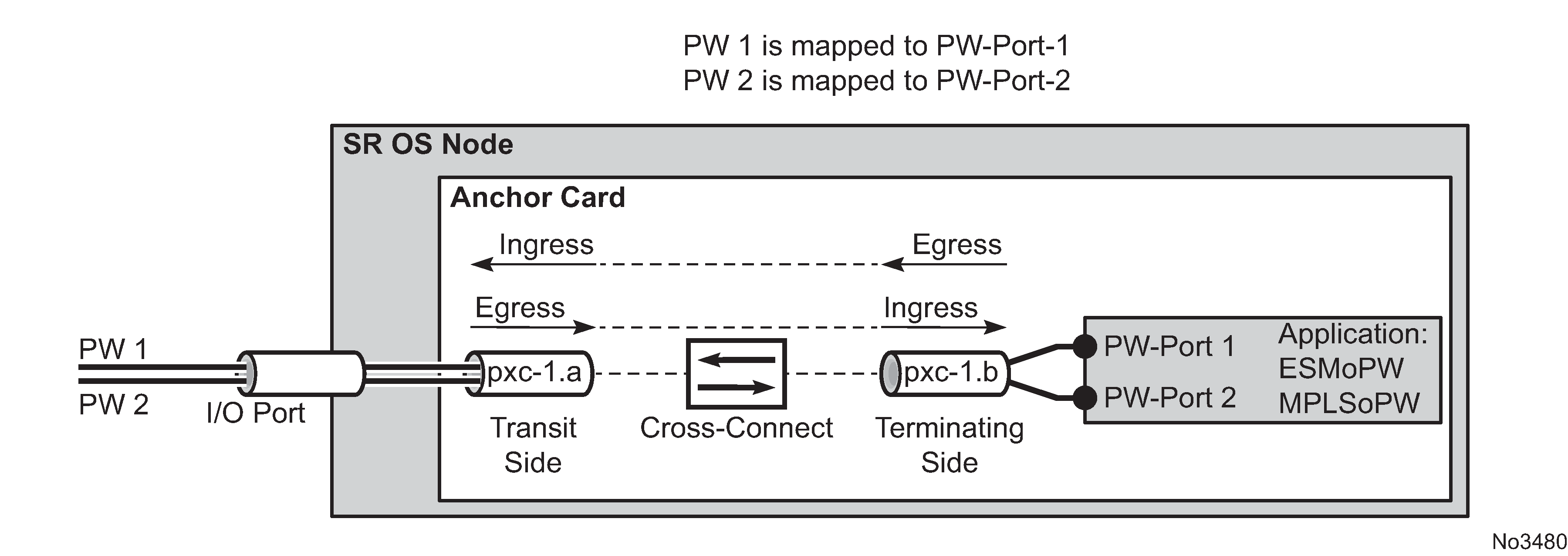
Parameters associated with the PXC sub-ports or PXC based LAGs (QoS, lag-profiles, and so on) are accessible/configurable through CLI. For example, the operator may apply an egress port-scheduler on sub-port pxc-1.b in Figure: Multiplexing PWs over PXC-based internal cross-connect to manage the sum of the bandwidth from associated PW-ports (PW-ports 1 and 2). To avoid confusion during configuration of PXC sub-ports /LAGs, a clear definition of reference points on the cross-connect created through FPE is required:
-
Terminating side of the cross-connect is closer to PW-ports (.b side)
-
Transit side of the cross-connect is closer to I/O ports (.a side)
Because the creation of the cross-connect on FPE based PW-ports is highly automated through and FPE configurations, the SR OS system:
-
Assign PXC sub-ports .a to the transit side, and PXC sub-ports .b to the terminating side in case that a single PXC is used; see Figure: Assign PXC sub ports .
Figure: Assign PXC sub ports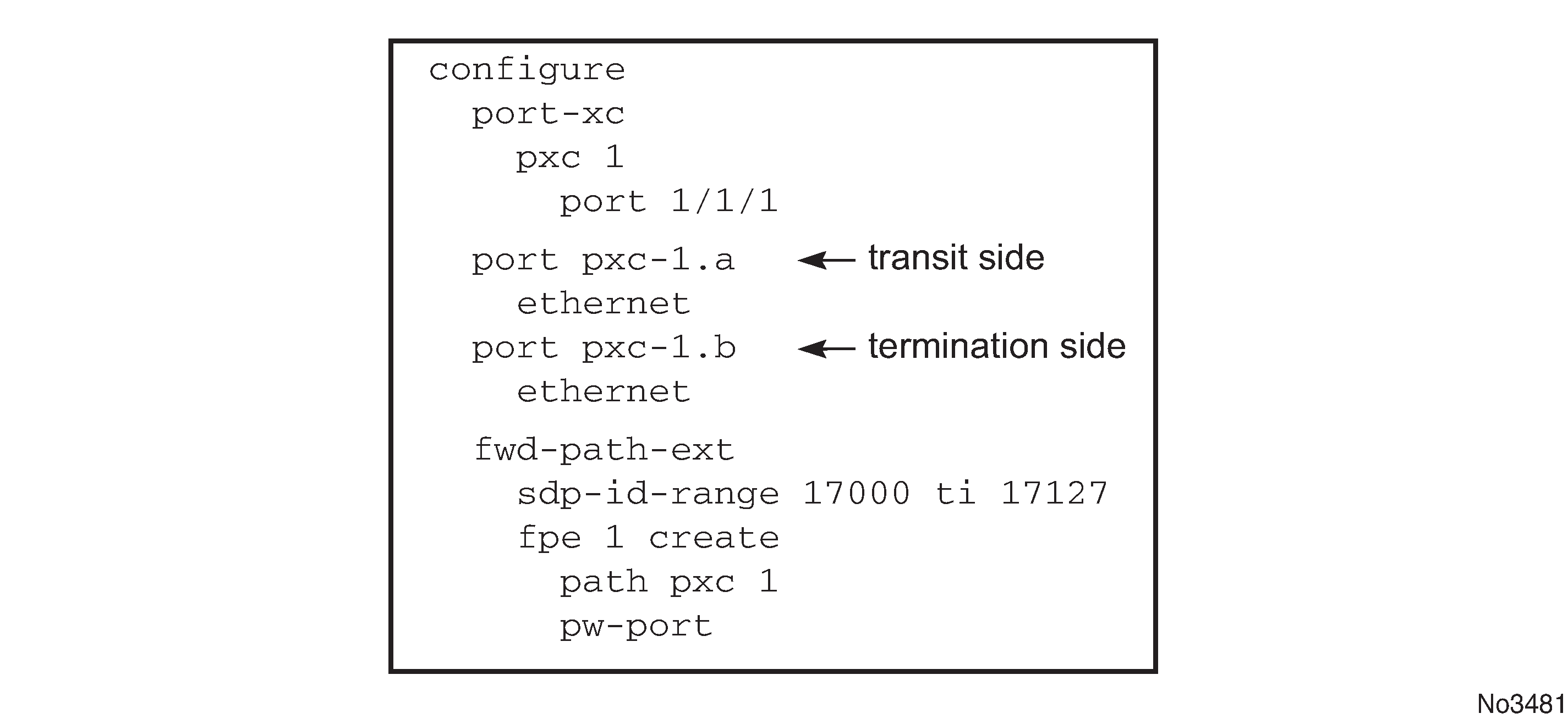
-
Assign the xc-a LAG to the transit side, and the xc-b LAG to the terminating side if that a PXC based LAG is used; see Figure: Assign the LAG .
Figure: Assign the LAG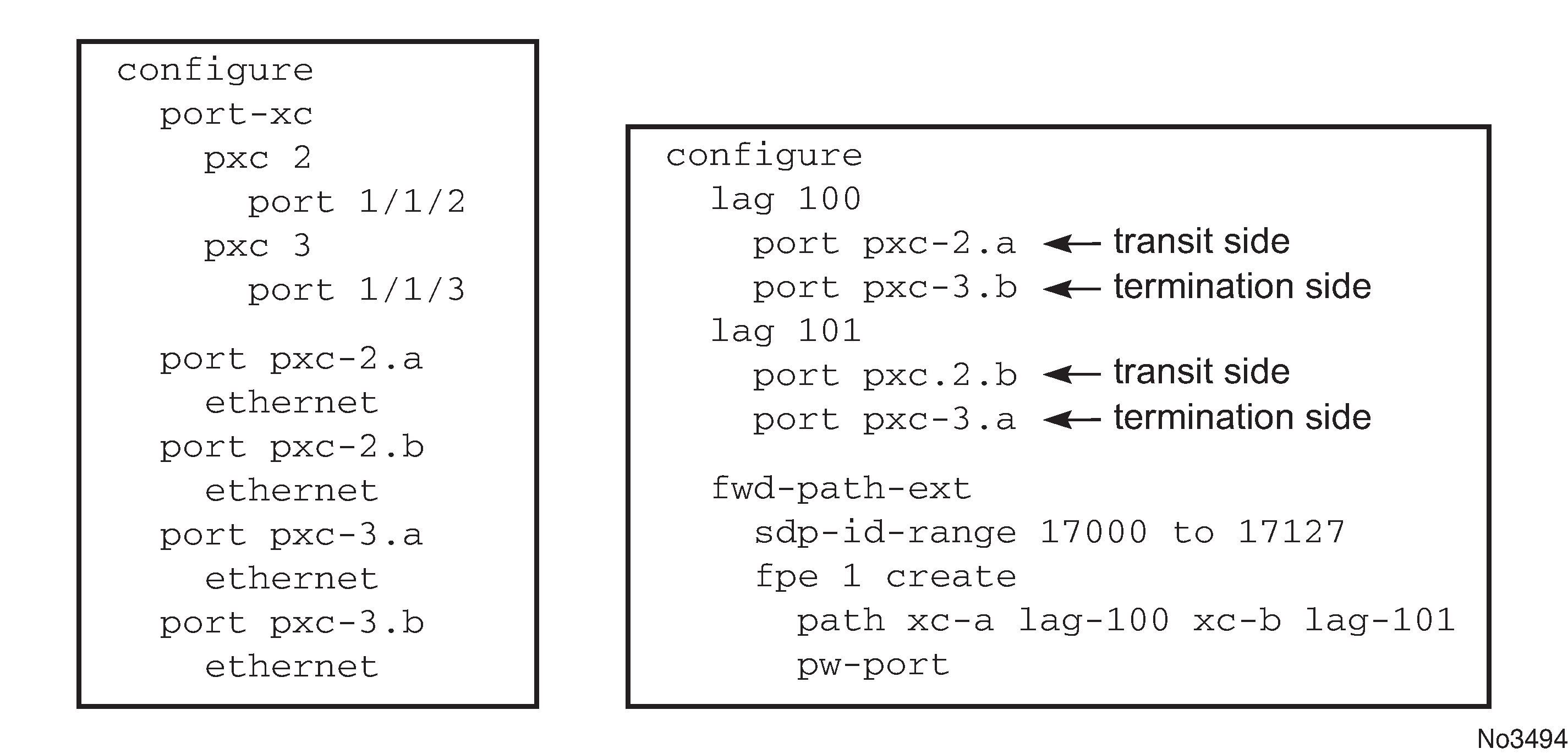
xc-a and xc-b can be associated with any PXC based LAG ID. For example, the following path configuration is allowed: xc-a with lag-id 100 (which includes pxc sub-ports pxc-2.a and pxc-3.b) and xc-b with lag-id 101 (which includes pxc sub-ports pxc-3.a and pxc-2.b). Regardless of the pxc sub-ports that are assigned to respective LAGs, the xc-a side of the path is used as the transit side of the cross-connect, while the xc-b side of the path is used as the termination side of the cross-connect.