The support of SR-TE in the data path requires that the ingress LER pushes a label stack where each label represents a hop, a TE link, or a node, in the ERO for the LSP path computed by the router or the PCE. However, only the label and the outgoing interface to the first strict/loose hop in the ERO factor into the forwarding decision of the ingress LER. In other words, the SR-TE LSP only needs to track the reachability of the first strict/loose hop.
This actually represents the NHLFE of the SR shortest path tunnel to the first strict/loose hop. SR OS keeps the SR shortest path tunnel to a downstream node SID or adjacency SID in the tunnel table and so its NHLFE is readily available. The rest of the label stack is not meaningful to the forwarding decision. In this document, ‟super NHLFE” refers to this part of the label stack because it can have a much larger size.
As a result, an SR-TE LSP is modeled in the ingress LER data path as a hierarchical LSP with the super NHLFE is tunneled over the NHLFE of the SR shortest path tunnel to the first strict/loose hop in the SR-TE LSP path ERO.
Some characteristics of this design are as follows:
The design saves on NHLFE usage. When many SR TE LSPs are going to the same first hop, they are riding the same SR shortest path tunnel, and each consumes one super NHLFE but they are pointing to a single NHLFE, or set of NHLFEs when ECMP exists for the first strict/loose hop, of the first hop SR tunnel.
Also, the ingress LER does not need to program a separate backup super NHLFE. Instead, the single super NHLFE automatically begins forwarding packets over the LFA backup path of the SR tunnel to the first hop as soon as the SR tunnel LFA backup path is activated.
When the path of a SR-TE LSP contains a maximum of two SIDs, that is the destination SID and one additional loose or strict-hop SID, the SR-TE LSP uses a hierarchy consisting of a regular NHLFE pointing to the NHLFE of top SID corresponding to the first loose or strict hop.
If the first segment is a node SID tunnel and multiple next-hops exist, then ECMP spraying is supported at the ingress LER.
If the first hop SR tunnel, node or adjacency SID, goes down the SR module informs MPLS that outer tunnel down and MPLS brings the SR-TE LSP down and requests SR to delete the SR-TE LSP in IOM.
The data path behavior at LSR and egress LER for an SR-TE LSP is similar to that of shortest path tunnel because there is no tunnel state in these nodes. The forwarding of the packet is based on processing the incoming label stack consisting of a node SID and, or adjacency SID label. If the ILM is for a node SID and multiple next-hops exist, then ECMP spraying is supported at the LSR.
The link-protect LFA backup next hop for an adjacency SID can be programmed at the ingress LER and LSR nodes (as described in SR-TE LSP protection).
A maximum of 12 labels, including all transport, service, hash, and OAM labels, can be pushed. The label stack size for the SR-TE LSP can be 1 to 11 labels, with a default value of 6.
The maximum value of 11 is obtained for an SR-TE LSP whose path is not protected via FRR backup and with no entropy or hash label feature enabled when such an LSP is used as a shortcut for an IGP IPv4/IPv6 prefix or as a shortcut for BGP IPv4/IPv6. In this case, the IPv6 prefix requires pushing the IPv6 explicit-null label at the bottom of the stack. This leaves 11 labels for the SR-TE LSP.
The default value of 6 is obtained in the worst cases, such as forwarding a vprn-ping packet for an inter-AS VPN-IP prefix in Option C:
6 SR-TE labels + 1 remote LFA SR label + BGP 3107 label + ELI (RFC 6790) + EL (entropy label) + service label + OAM Router Alert label = 12 labels.
The label stack size manipulation includes the following LER and LSR roles:
LER role
push up to 12 labels
pop-up to 8 labels of which 4 labels can be transport labels
LSR role
pop-up to 5 labels and swap one label for a total of 6 labels
LSR hash of a packet with up to 16 labels
An example of the label stack pushed by the ingress LER and by a LSR acting as a PLR is illustrated in Figure: SR-TE LSP label stack programming.
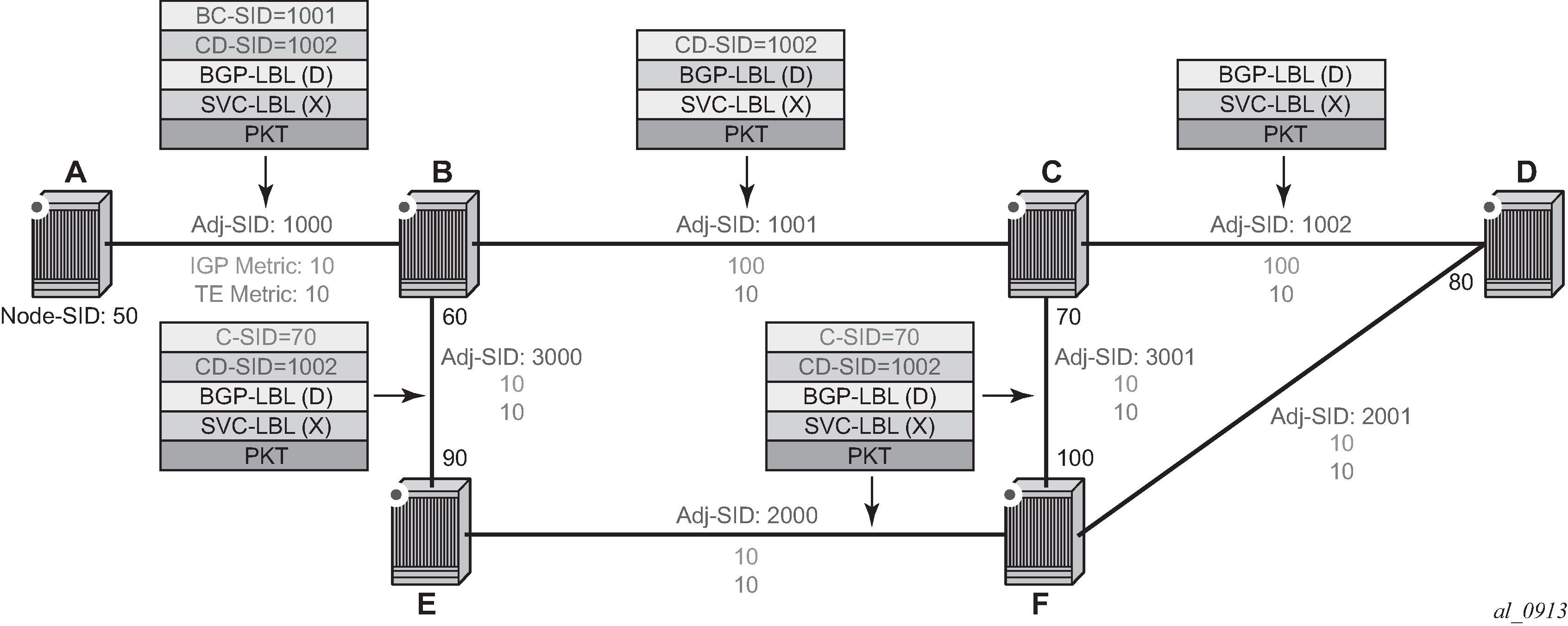
On node A, the user configures an SR-TE LSP to node D with a list of explicit strict hops mapping to the adjacency SID of links: A-B, B-C, and C-D.
Ingress LER A programs a super NHLFE consisting of the label for the adjacency over link C-D and points it to the already-programmed NHLFE of the SR tunnel of its local adjacency over link A-B. The latter NHLFE has the top label and also the outgoing interface to send the packet to.
LSR Node B already programmed the primary NHLFE for the adjacency SID over link C-D and has the ILM with label 1001 point to it. In addition, node B pre-programs the link-protect LFA backup next hop for link B-C and point the same ILM to it.
VPRN service in node A forwards a packet to the VPN-IPv4 prefix X advertised by BGP peer D. Figure: SR-TE LSP label stack programming shows the resulting data path at each node for the primary path and for the FRR backup path at LSR B.