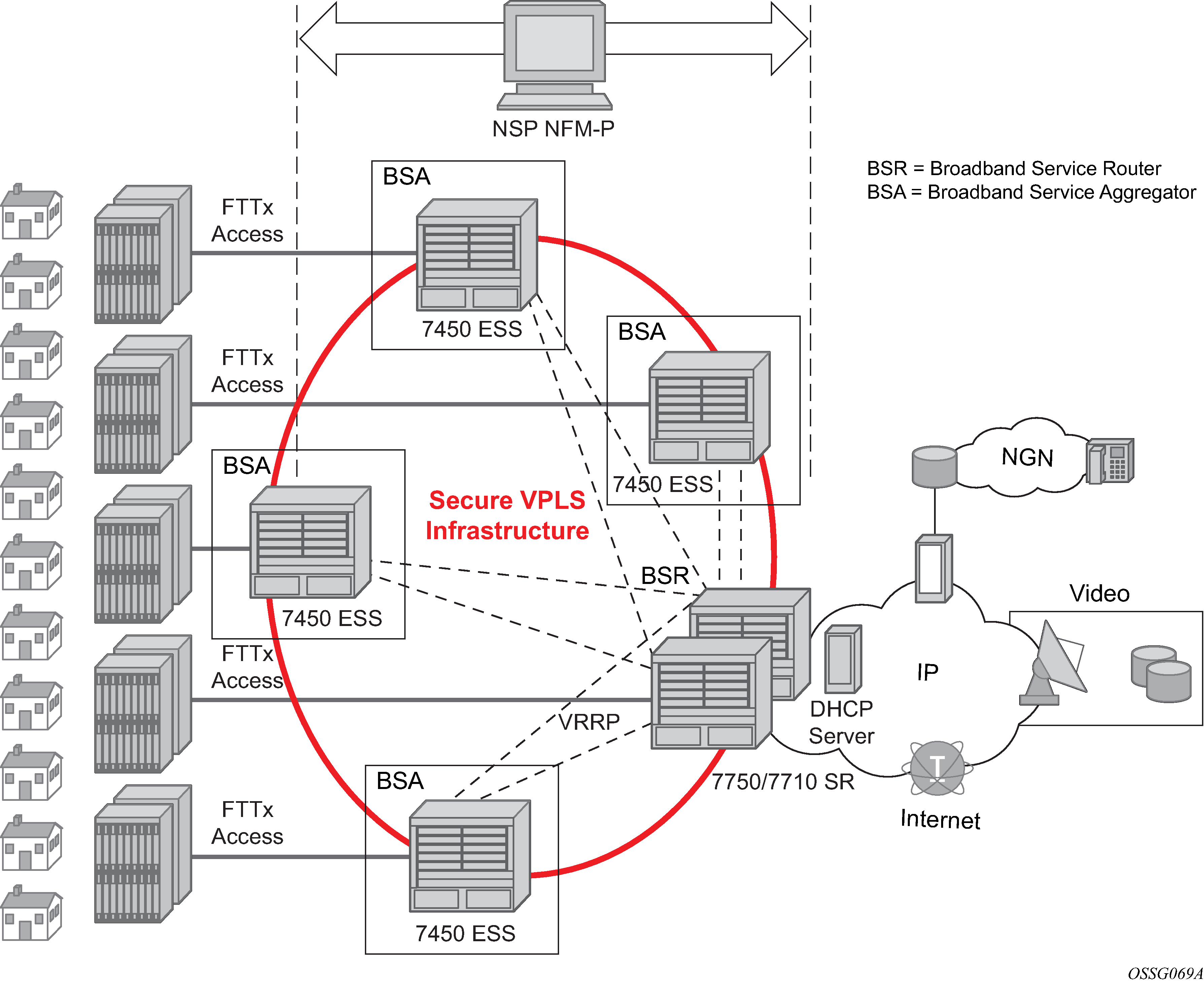
The TPSDA architecture (Figure: Nokia’s Triple Play Service Delivery Architecture), is based on two major network elements optimized for their respective roles, the Broadband Service Aggregator (BSA) and the Broadband Service Router (BSR). An important characteristic of BSAs and BSRs is that they effectively form a distributed virtual node with the BSAs performing subscriber-specific functions where the various functions scale, and the BSRs providing the routing intelligence where it is most cost-effective.
The Nokia 7450 ESS and 7750 SR OS, respectively, provide the BSA and BSR functionalities in TPSDA. Both are managed as a single virtual node using Nokia's NSP NFM-P, which provides a unified interface for streamlined service and policy activation across the distributed elements of the TPSDA architecture, including VPLS, QoS, multicasting, security, filtering, and accounting.

Digital subscriber line access multiplexers (DSLAMs) or other access nodes are connected to Ethernet access ports on the BSA. Typically a single VLAN per subscriber is configured between the access node and the BSA. A VLAN per subscriber provides a persistent context against which per-subscriber policies (QoS, filtering, accounting) can be applied in the BSA.
Scaling of traffic and services is achieved by dividing the Layer 2 and Layer 3 functions between the BSA and BSR and by distributing key service delivery functions. BSAs are more distributed than BSRs, cost-effectively scaling per-subscriber policy enforcement.
The BSA is a high-capacity Ethernet-centric aggregation device that supports hundreds of gigabit Ethernet ports, tens of thousands of filter policies, and tens of thousands of queues. The BSA incorporates wire speed security, per-subscriber service queuing, scheduling, accounting, and filtering.
BSAs aggregate traffic for all services toward the BSR. The BSR terminates the Layer 2 access and routes over IP/MPLS (Multi-Protocol Label Switching) with support for a full set of MPLS and IP routing protocols, including multicast routing. The BSR supports hundreds of ports and sophisticated QoS for per-service and per-content or source differentiation.
The connectivity between BSAs and BSRs is a Layer 2 forwarding model shown in Figure: Nokia’s Triple Play Service Delivery Architecture above as a secure VPLS infrastructure. This refers to the fact that the BSA-BSR interconnections form a multipoint Ethernet network with security extensions to prevent unauthorized communication, denial of service, and theft of service. One of the advantages of using VPLS for this application is that VPLS instances can be automatically established over both ‛hub and spoke’ and ring topologies providing sub-50 ms resilience. Regardless of the fiber plant layout, VPLS enables a full mesh to be created between BSA and BSR nodes, ensuring efficient traffic distribution and resilience to node or fiber failure.
Other unique features of the BSA and BSR that contribute to this secure VPLS infrastructure are:
-
Using Residential Split Horizon Groups (RSHG), direct user-user bridging is automatically prohibited, without the need for address-specific ACLs.
-
RSHG combined with the ARP reply agent perform ARP and broadcast suppression to ensure that addressing information is restricted.
-
Protection against theft of service and denial of service is provided by MAC or IP filters automatically populated using DHCP snooping, and by MAC pinning.
-
Using the RADIUS interface, is possible to perform RADIUS authentication of users before allowing a DHCP discover to progress into the network.