Figure: Dual homing to two PEs depicts dual homing to two different PE nodes. The actual architecture can be based on a single DSLAM having two connections to two different PEs (using MC-LAG) or ring of DSLAMs dual-connected to redundant pair of PEs.
Similarly to previous configuration, both aggregation models (VLAN-per-subscriber or VLAN-per-service) are applicable.
Configurations include:
Loop resolution and failure recovery — Can be based on MC-LAG or mVPLS.
DHCP-lease-state persistency — Stores all required information to recover from node failure.
DHCP-lease-state synchronization — A mechanism to synchronize the DHCP lease-state between two PE nodes in the scope of redundancy groups (a group of SAPs used for dual homing).
IGMP snooping state synchronization — Similarly to DHCP lease-state synchronization, IGMP snooping state is synchronized to ensure fast switchover between PE nodes. In a VPLS network, a BTV stream is typically available in all PE nodes (the ring interconnecting all PEs with Mcast routers is typically used) so the switch over can be purely driven by RSTP or MC-LAG.
ARP reply agent responses
The ARP reply agent can response to ARP requests addressing a host behind the specific SAP if the SAP is in a forwarding state. This prevents the FDB table in the VPLS from being ‟poisoned” by ARP responses generated by the node with a SAP in a blocking state (see Figure: Layer 2 CO dual homing - network diagram ).
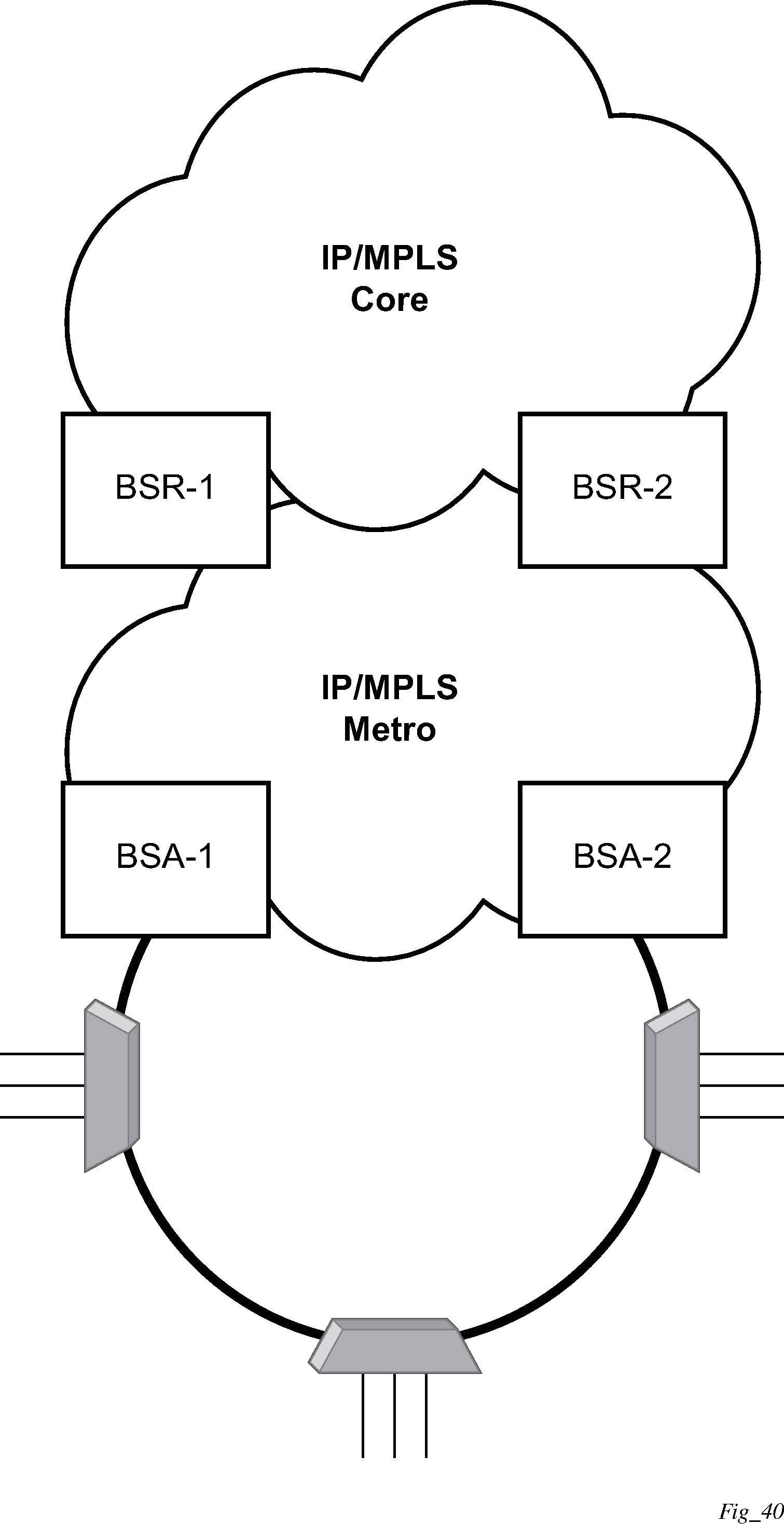
Figure: Layer 2 CO dual homing - network diagram shows a typical configuration of network model based on Layer 2 CO model. Individual rings of access nodes are aggregated at BSA level in one (or multiple) VPLS services. At higher aggregation levels (the BSR), individual BSAs are connected to Layer 3 interfaces (IES or VPRN) by spoke SDP termination. Every Layer 3 interface at BSR level aggregates all subscribers in one subnet.
Typically, BTV service distribution is implemented in a separate VPLS service with a separate SAP per access-node. This extra VPLS is not explicitly indicated in Figure: Layer 2 CO dual homing - network diagram (and subsequent figures) but the descriptions refer to its presence.
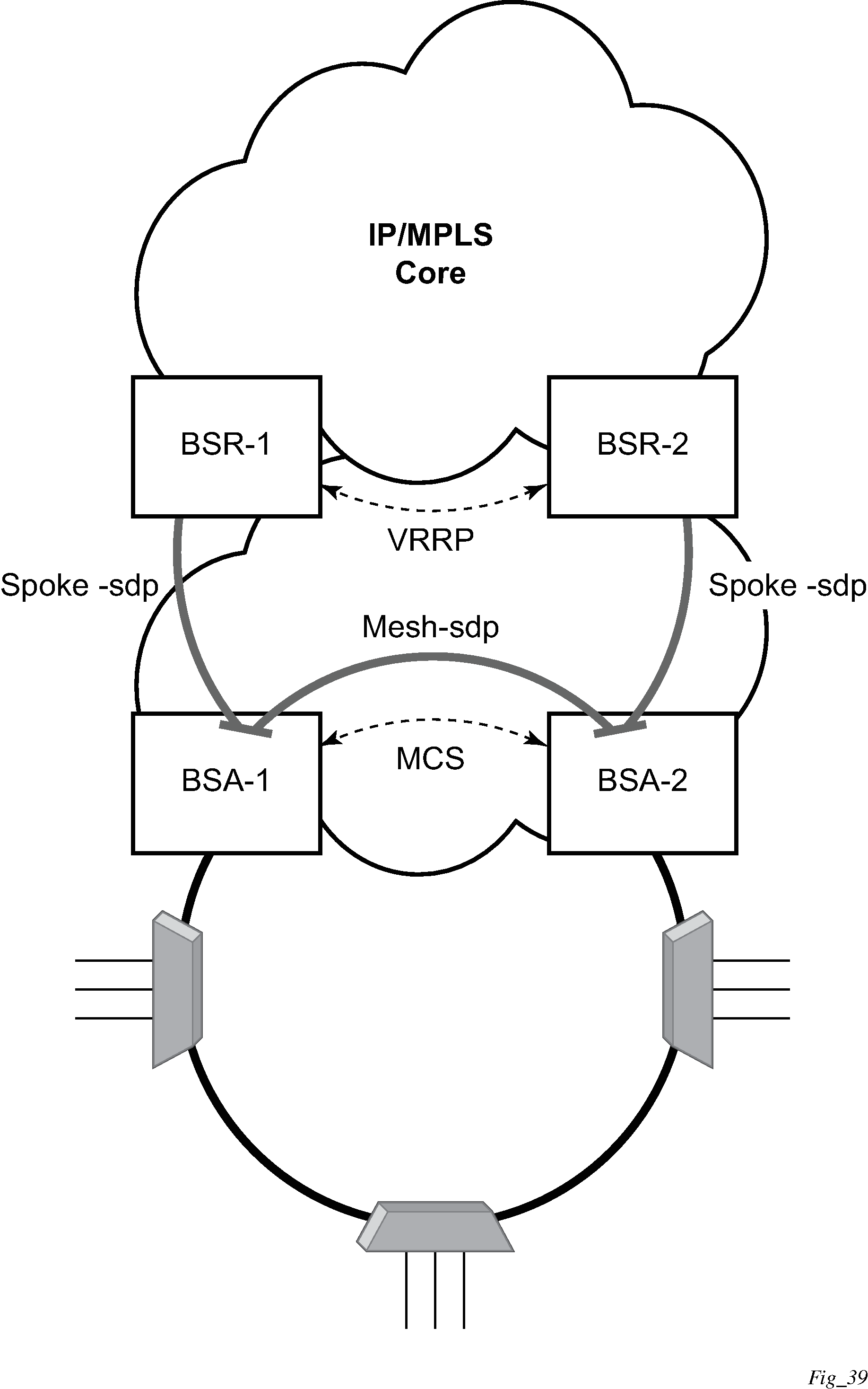
From a configuration point of view in this model, it is assumed that all subscriber management features are enabled at the BSA level and that synchronization of the information (using multi-chassis synchronization) is configured between redundant pair nodes (BSA-1 and BSA-2 shown in Figure: Layer 2 CO dual homing - network diagram ). The multi-chassis synchronization connection is used only for synchronizing active subscriber host database and operates independently from dual-homing connectivity control. At the BSR level, there are no subscriber management features enabled.
The operation of redundancy at the BSR level through VRRP is the same as dual homing based on MC-LAG. The operation of dual homing at BSA level is based on two mechanisms. Ring control connection between two BSAs have two components, in-band and out-of-band communication. With in-band communication, BFD session between BSA-1 and BSA-2 running through the access ring and using dedicated IES/VPRN interface configured on both nodes. This connection uses a separate VLAN throughout the ring. The access nodes provides transparent bridging for this VLAN. The BFD session is used to continuously verify the integrity of the ring and to detect a failure somewhere in the ring.
With out-of-band communication, the communication channel is used by BSA nodes to exchange information about the reachability of individual access nodes as well as basic configurations to verify the consistency of the ring. The configuration information is synchronized through multi-chassis synchronization and therefore it is mandatory to enable multi-chassis synchronization between two nodes using the multi-chassis-ring concept.
In addition, the communication channel used by MC-LAG or MC-APS control protocol is used to exchange some event information. The use of this channel is transparent to the user.
Ring node connectivity check continuously checks the reachability of individual access nodes in the ring. The session carrying the connection is conducted on separate VLAN, typically common for all access nodes. SHCV causes no interoperability problems.