Figure: Dual homing ring under steady-state condition illustrates the operation of the dual-homed ring. The steady state is achieved when both nodes are configured in a consistent way and the peering relation is up. The multi-chassis ring must be provisioned consistently between two nodes.
In-Band Ring Control Connection (IB-RCC) is in an operationally UP state. Note that this connection is set up using a bidirectional forwarding session between IP interfaces on BSA-1 and BSA-2.
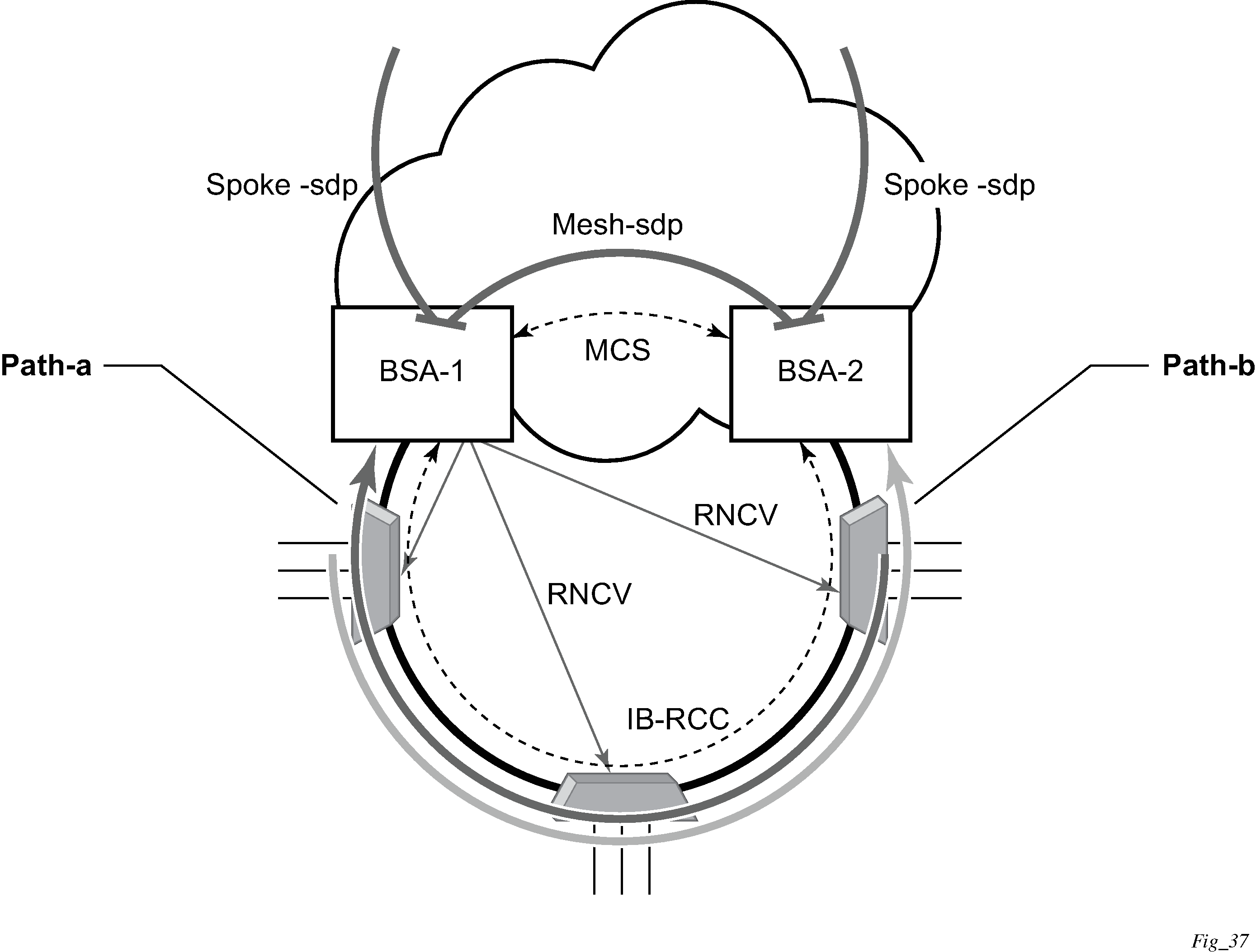
In Figure: Dual homing ring under steady-state condition, the ring is fully closed and every access node has two possible paths toward the VPLS core. Figure: Dual homing ring under steady-state condition refers to these as path-a and path-b. To avoid the loop created by the ring, only one of the paths can be used by any specific ring node for any specified VLAN. The assignment of the individual VLANs to path-a or path-b, respectively, has to be provisioned on both BSAs.
The selection of the primary BSA for both paths is based on the IP address of the interface used for IB-RCC communication (bidirectional forwarding session). The BSA with the lower IP address of the interface used as IB-RCC channel becomes the primary for ring nodes and their respective VLANs assigned to path-a. The primary for path-b is the other BSA.
In this example, each path in the ring has a primary and standby BSA. The functionality of both devices in steady state are as follows:
In the primary BSA:
All SAPs that belong to the path where the specific BSA is the primary node are operationally UP and all FDB entries of subscriber hosts associated with these SAPs point to their respective SAPs.
The primary BSA of a path performs periodical Ring Node Connectivity Verification (RNCV) check to all ring nodes.
In case of a RNCV failure, the respective alarm is raised. The loss of RNCV to the specified ring node does not trigger any switchover action even if the other BSA appears to have the connection to that ring node. If the BFD session is up, the ring is considered closed and the primary or standby behavior is driven solely by provisioning of the individual paths.
The ARP reply agent replies to ARP requests addressing subscriber hosts for which the BSA is primary.
In the standby BSA:
All SAPs that belong to a BSA’s path, the standby is operationally down and all FDB entries of subscriber hosts associated with those SAPs point toward the SDP connecting to the primary BSA (also called a shunt SDP).
In both primary and standby BSAs:
The information about individual path assignments is exchanged between both BSAs through multi-chassis synchronization communication channel and conflicting SAPs (being assigned to different paths on both BSA nodes) are forced to path-a (the default behavior).
For IGMP snooping, the corresponding multi-chassis IDs are targeting all subscriber-facing SAPs on both nodes. On the standby BSA node, the corresponding SAPs are in an operationally down state to prevent the MC traffic be injected on the ring twice.