Multi-chassis LAG is a method of providing redundant Layer 2/3 access connectivity that extends beyond link level protection by allowing two systems to share a common LAG end point.
The multi-service access node (MSAN) node is connected with multiple links toward a redundant pair of Layer 2/3 aggregation nodes such that both link and node level redundancy, are provided. By using a multi-chassis LAG protocol, the paired Layer 2/3 aggregation nodes (referred to as redundant-pair) appears to be a single node utilizing LACP toward the access node. The multi-chassis LAG protocol between a redundant-pair ensures a synchronized forwarding plane to and from the access node and synchronizes the link state information between the redundant-pair nodes such that correct LACP messaging is provided to the access node from both redundant-pair nodes.
To ensure SLAs and deterministic forwarding characteristics between the access and the redundant-pair node, the multi-chassis LAG function provides an active/standby operation to and from the access node. LACP is used to manage the available LAG links into active and standby states such that only links from 1 aggregation node are active at a time to/from the access node.
Alternatively, when access nodes do not support LACP, the power-off option can be used to enforce the active/standby operation. In this case, the standby ports are trx_disabled (power off transmitter) to prevent usage of the LAG member by the access-node. Characteristics related to MC are:
Selection of the common system ID, system-priority and administrative-key are used in LACP messages so partner systems consider all links as the part of the same LAG.
Extension of selection algorithm to allow selection of active sub-group.
The sub-group definition in LAG context is still local to the single box, meaning that even if sub-groups configured on two different systems have the same sub-group-id they are still considered as two separate subgroups within a specified LAG.
Multiple sub-groups per PE in an MC-LAG is supported.
In case there is a tie in the selection algorithm, for example, two sub-groups with identical aggregate weight (or number of active links) the group which is local to the system with lower system LACP priority and LAG system ID is taken.
Providing inter-chassis communication channel allows inter-chassis communication to support LACP on both system. This communication channel enables the following:
Supports connections at the IP level which do not require a direct link between two nodes. The IP address configured at the neighbor system is one of the addresses of the system (interface or loop-back IP address).
The communication protocol provides heartbeat mechanism to enhance robustness of the MC-LAG operation and detecting node failures.
Support for operator actions on any node that force an operational change.
The LAG group-ids do not have to match between neighbor systems. At the same time, there can be multiple LAG groups between the same pair of neighbors.
Verification that the physical characteristics, such as speed and auto-negotiation is configured and initiates operator notifications (traps) if errors exist. Consistency of MC-LAG configuration (system-id, administrative-key and system-priority) is provided. Similarly, load-balancing mode of operation must be consistently configured on both nodes.
Traffic over the signaling link is encrypted using a user configurable message digest key.
MC-LAG function provides active/stand-by status to other software applications to build a reliable solution.
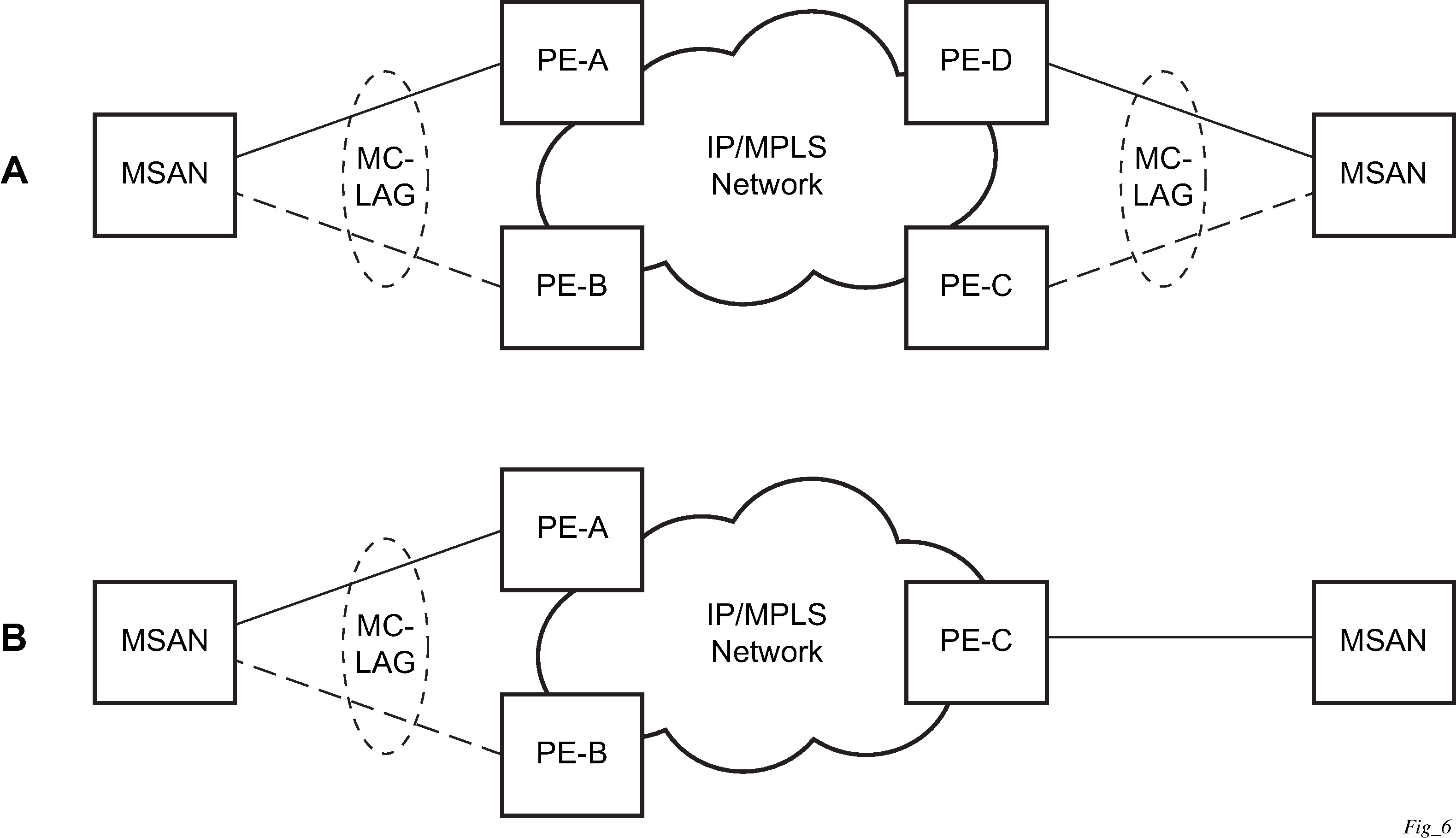
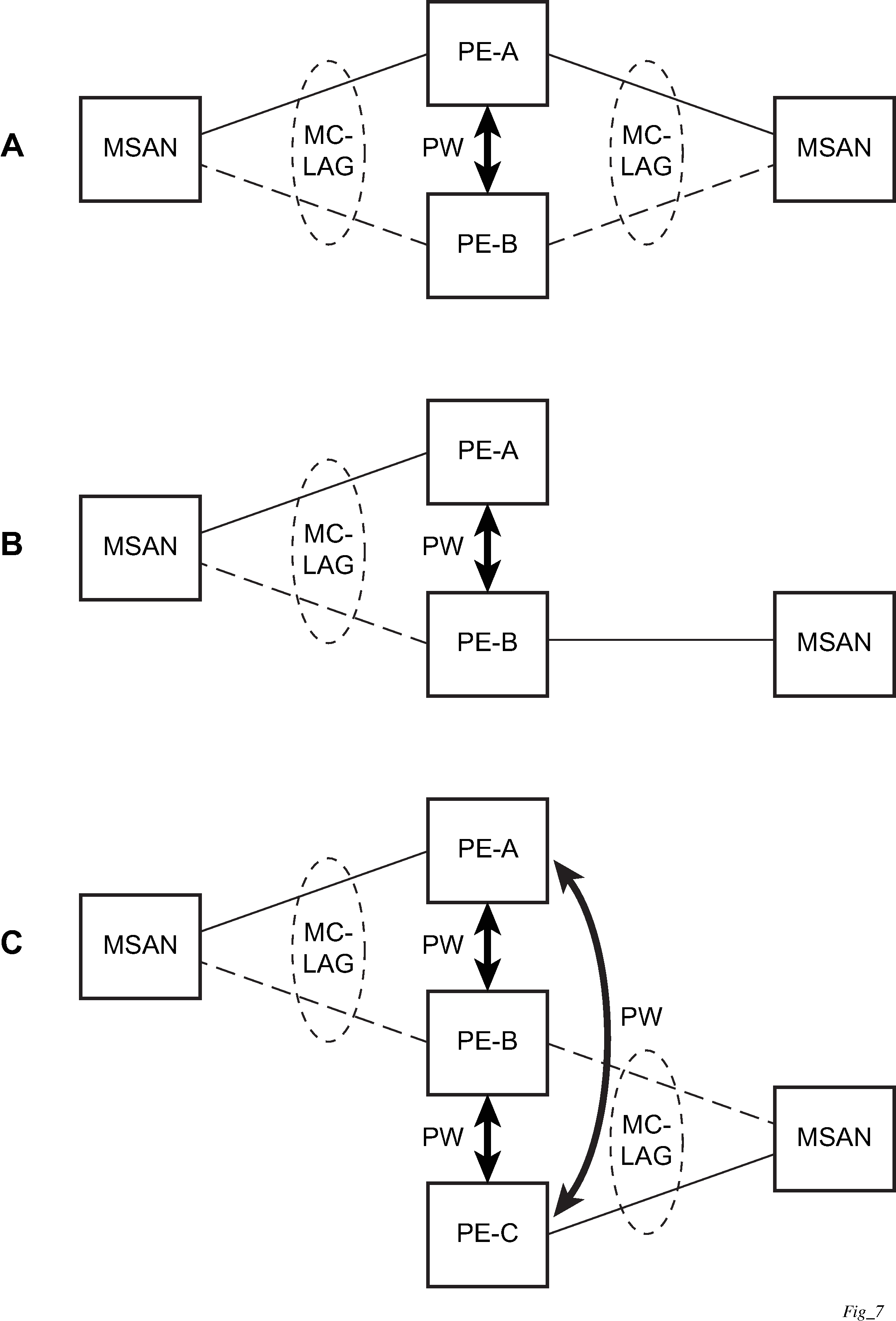
Figure: MC-LAG Layer 2 dual homing to remote PE pairs and Figure: MC-LAG Layer 2 dual homing to local PE pairs show the different combinations of MC-LAG attachments that are supported. The supported configurations can be sub-divided into following sub-groups:
Dual-homing to remote PE pairs
both end-points attached with MC-LAG
one end-point attached
Dual-homing to local PE pair
both end-points attached with MC-LAG
one end-point attached with MC-LAG
both end-points attached with MC-LAG to two overlapping pairs


The forwarding behavior of the nodes abide by the following principles. Note that logical destination (actual forwarding decision) is primarily determined by the service (VPLS or VLL) and the principle below applies only if destination or source is based on MC-LAG:
Packets received from the network are forwarded to all local active links of the specific destination-sap based on conversation hashing. In case there are no local active links, the packets are cross-connected to inter-chassis pseudowire.
Packets received from the MC-LAG sap are forwarded to active destination pseudowire or active local links of destination-sap. In case there are no such objects available at the local node, the packets are cross-connected to inter-chassis pseudowire.