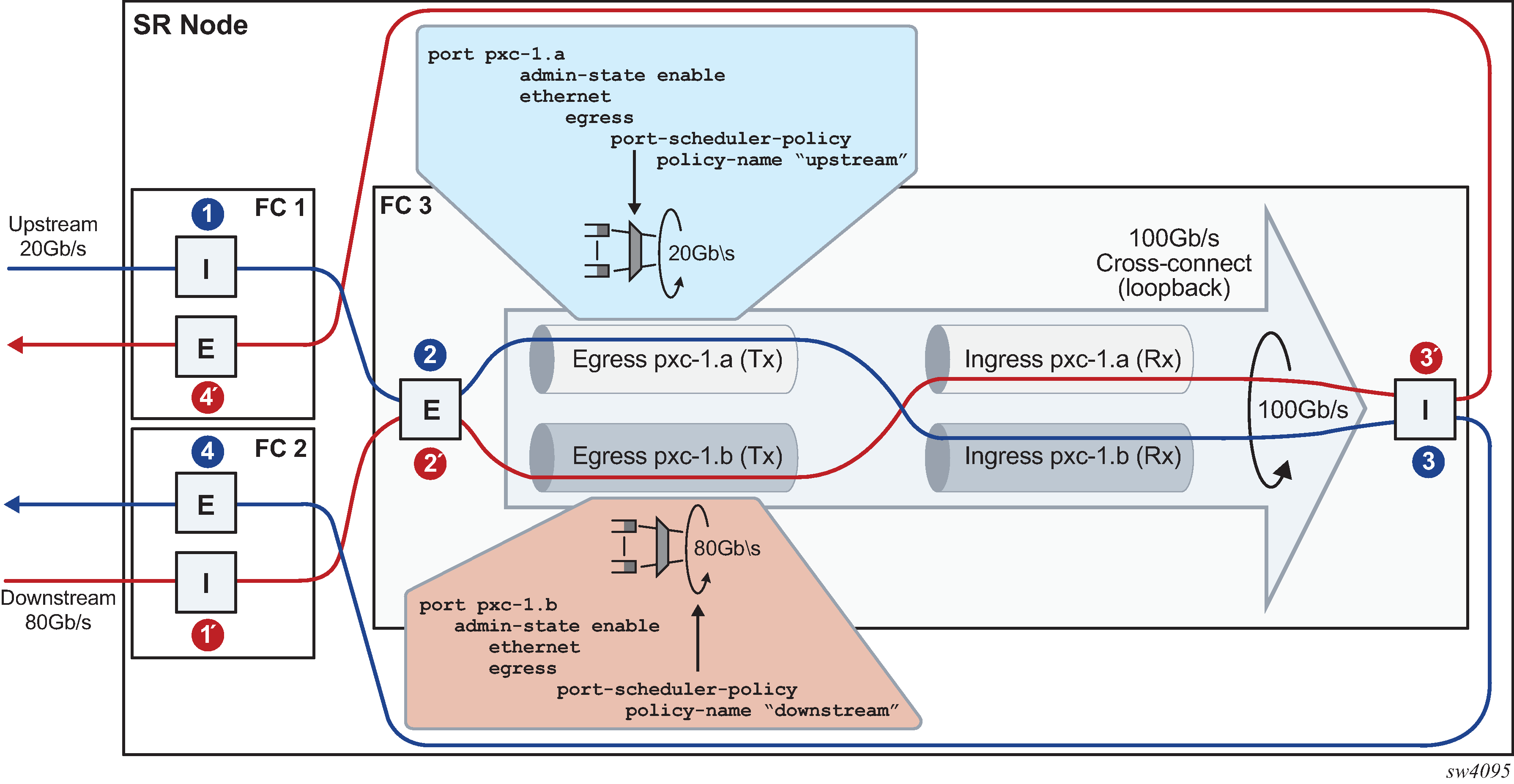
The network operator must understand the concept of the PXC sub-ports described in Port-based PXC for correct egress QoS configuration in the traffic manager (Q).
The following summarizes key points for the PXC sub ports:
Each subport (pxc-id.a and pxc-id.b) in a PXC is, in the context of egress QoS, treated as a separate port with its own port scheduler policy.
Both sub-ports are created on top of the same loopback configuration (port- based or MAC-based). For faceplate ports, this bandwidth is determined by the port capabilities (for example, a 100 Gb\s port versus a 400 Gb\s port) and for the MAC loopback, this bandwidth is configurable.
Funneling traffic from two PXC sub-ports through the same loopback requires separate bandwidth management for each PXC sub-ports. The sum of the configured bandwidth caps for the Egress Port Scheduler (EPS) under the two PXC sub-ports should not exceed the bandwidth capacity of the underlying loopback. Figure: Bandwidth management on PXC sub-ports shows an example of this concept where each PXC sub-port is divided into two parts, the Tx or the egress part and the Rx or the ingress part. Figure: Bandwidth management on PXC sub-ports shows bidirectional traffic entering and exiting the SR node at forwarding complex 1 and 2, with PXC processing on forwarding complex 3. In the upstream direction, traffic enters SR node at the ingress forwarding complex 1 at point (1) and is redirected to the PXC for additional processing, points (2) and (3). From there, traffic is sent by the egress forwarding complex 2 out of the node, at point (4).
Similar logic can be followed in the downstream (opposite) direction where the traffic enters the ingress forwarding complex 2 at point (1’), it is redirected to the same PXC on forwarding complex 3 and exists the node on forwarding complex 1 at point (4’).
In this example with the maximum loopback bandwidth of 100 Gb\s, port-schedulers under the PXC egress subports must be configured to support their respective anticipated bandwidth in each direction (20 Gb\s upstream and 80 Gb\s downstream), for the total bandwidth of 100 Gb\s supported on the cross-connect.

Traffic traversing PXC contains an overhead of 4 bytes per packet that are attributed to the internal VLAN tag used for PXC sub-port identification within the SR node. However, these 4 bytes are not accounted for in the configured QoS rates. Therefore, the operator should take this into consideration when configuring rates on QoS objects under PXC ports.