This section discusses the details of the Ethernet tunneling for PBB. The main solution components are depicted in Figure: PBB-Epipe with B-VPLS over Ethernet tunnel.
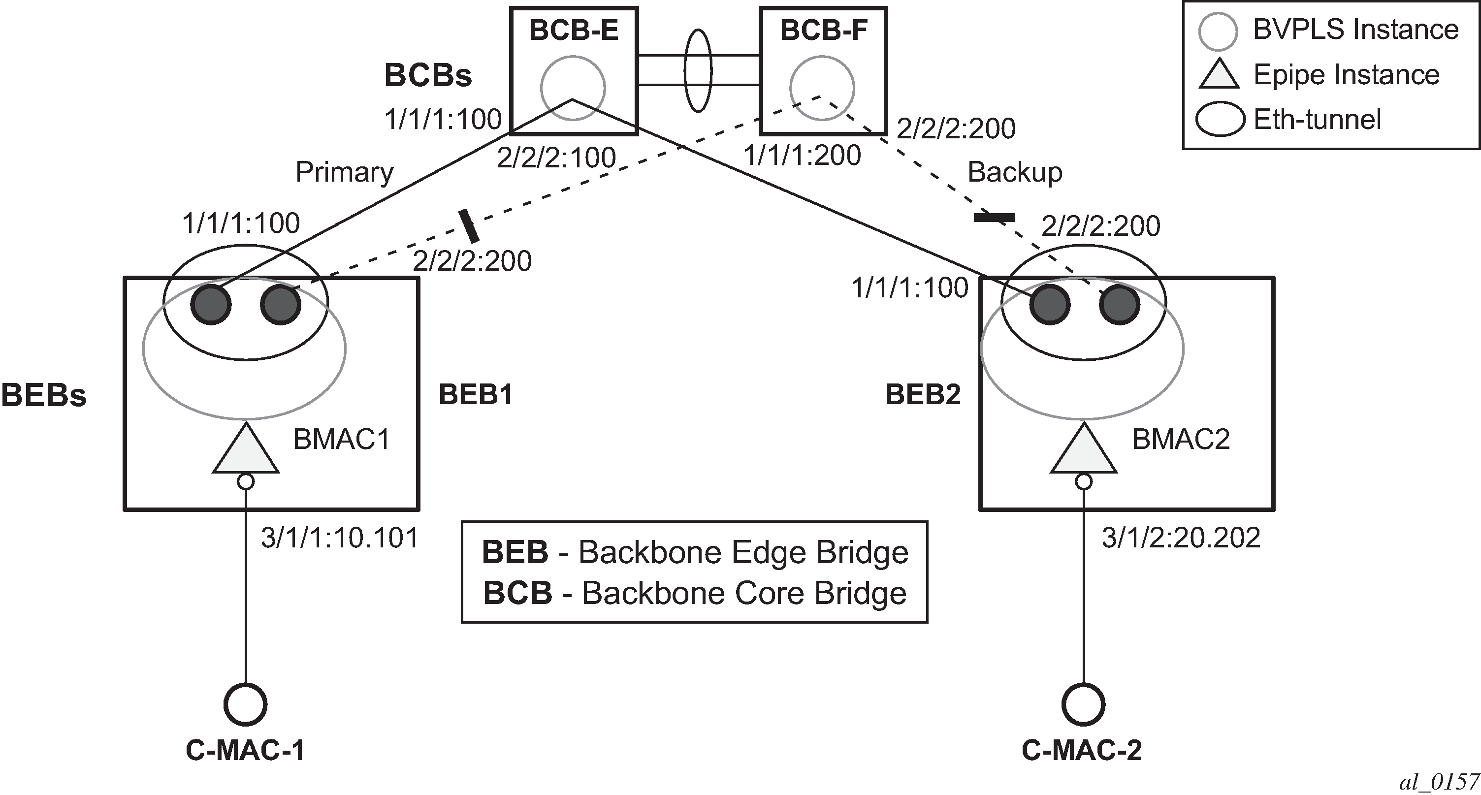
The PBB E-Line service is represented in the BEBs as a combination of an Epipe mapped to a BVPLS instance. A eth-tunnel object is used to group two possible paths defined by specifying a member port and a control tag. In our example, the blue-circle representing the eth-tunnel is associating in a protection group the two paths instantiated as (port, control-tag/bvid): a primary one of port 1/1/1, control-tag 100 and respectively a secondary one of port 2/2/2, control tag 200.
The BCBs devices stitch each BVID between different BEB-BCB links using either a VPLS or Epipe service. Epipe instances are recommended as the preferred option because of the increased tunnel scalability.
Fast failure detection on the primary and backup paths is provided using IEEE 802.1ag CCMs that can be configured to transmit at 10 msec interval. Alternatively, the link layer fault detection mechanisms like LoS/RDI or 802.3ah can be employed.
Path failover is controlled by an Ethernet protection module, based on standard G.8031 Ethernet Protection Switching. The Nokia implementation of Ethernet protection switching supports only the 1:1 model which is common practice for packet based services because it makes better use of available bandwidth. The following additional functions are provided by the protection module:
Synchronization between BEBs such that both send and receive on the same Ethernet path in stable state.
Revertive / non-revertive choices.
Compliant G.8031 control plane.
The secondary path requires a MEP to exchange the G.8031 APS PDUs. The following Ethernet CFM configuration in the eth-tunnel>path>eth-cfm>mep context can be used to enable the G.8031 protection without activating the Ethernet CCMs:
-
Create the domain (MD) in CFM.
-
Create the association (MA) in CFM and do not put remote MEPs.
-
Create the MEP.
-
Configure control-mep and no shutdown on the MEP.
-
Use the no ccm-enable command to keep the CCM transmission disabled.
If a MEP is required for troubleshooting issues on the primary path, the configuration described above for the secondary path must be used to enable the use of Link Layer OAM on the primary path.
LAG loadsharing is offered to complement G.8031 protected Ethernet tunnels for situations where unprotected VLAN services are to be offered on some or all of the same native Ethernet links.

In Figure: G.8031 P2P tunnels and LAG-like loadsharing coexistence , the G.8031 Ethernet tunnels are used by the B-SAPs mapped to the green BVPLS entities supporting the E-Line services. A LAG-like loadsharing solution is provided for the Multipoint BVPLS (white circles) supporting the E-LAN (IVPLS) services. The green G.8031 tunnels coexist with LAG-emulating Ethernet tunnels (loadsharing mode) on both BEB-BCB and BCB-BCB physical links.
The G.8031-controlled Ethernet tunnels select an active tunnel based on G.8031 APS operation, while emulated-LAG Ethernet tunnels hash traffic within the configured links. Upon failure of one of the links the emulated-LAG tunnels rehash traffic within the remaining links and fail the tunnel when the number of links breaches the minimum required (independent of G.8031-controlled Ethernet tunnels on the links shared emulated-LAG).