The IEEE model for PBB is organized around a B-component handling the provider backbone layer and an I-component concerned with the mapping of the customer/provider bridge (QinQ) domain (MACs, VLANs) to the provider backbone (B-MACs, B-VLANs): for example, the I-component contains the boundary between the customer and backbone MAC domains.
The Nokia implementation is extending the IEEE model for PBB to allow support for MPLS pseudowires using a chain of two VPLS context linked together as depicted in Figure: PBB mapping to VPLS configurations.
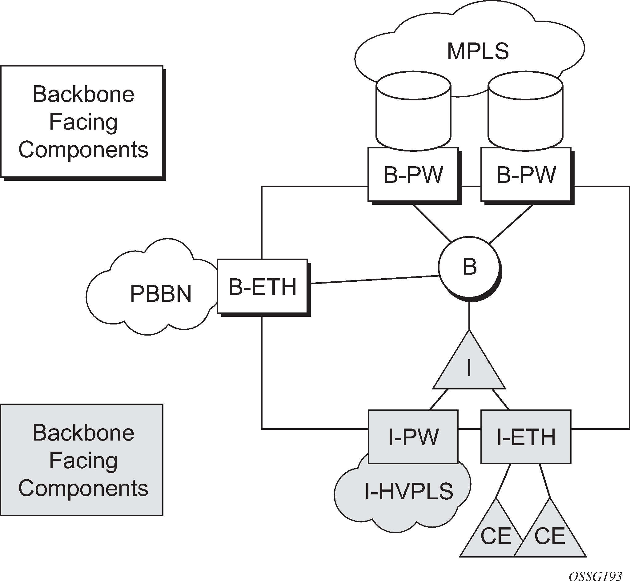
A VPLS context is used to provide the backbone switching component. The white circle marked B, referred to as backbone-VPLS (B-VPLS), operates on backbone MAC addresses providing a core multipoint infrastructure that may be used for one or multiple customer VPNs. The Nokia B-VPLS implementation allows the use of both native PBB and MPLS infrastructures.
Another VPLS context (I-VPLS) can be used to provide the multipoint I-component functionality emulating the E-LAN service (see the triangle marked ‟I” in Figure: PBB mapping to VPLS configurations). Similar to B-VPLS, I-VPLS inherits from the regular VPLS the pseudowire (SDP bindings) and native Ethernet (SAPs) handoffs accommodating this way different types of access: for example, direct customer link, QinQ or HVPLS.
To support PBB E-Line (point-to-point service), the use of an Epipe as I-component is allowed. All Ethernet SAPs supported by a regular Epipe are also supported in the PBB Epipe.