The use case described in the previous section is addressed by enhancing the existing native PBB solution to provide for blackhole avoidance.
The topology depicted in Figure: PBB active topology and access multihoming describes the details of the solution for the I-VPLS use case. Although the native PBB use case is used, the solution works the same for any other PBB infrastructure: for example, G.8031 Ethernet tunnels, pseudowire/MPLS, or a combination.
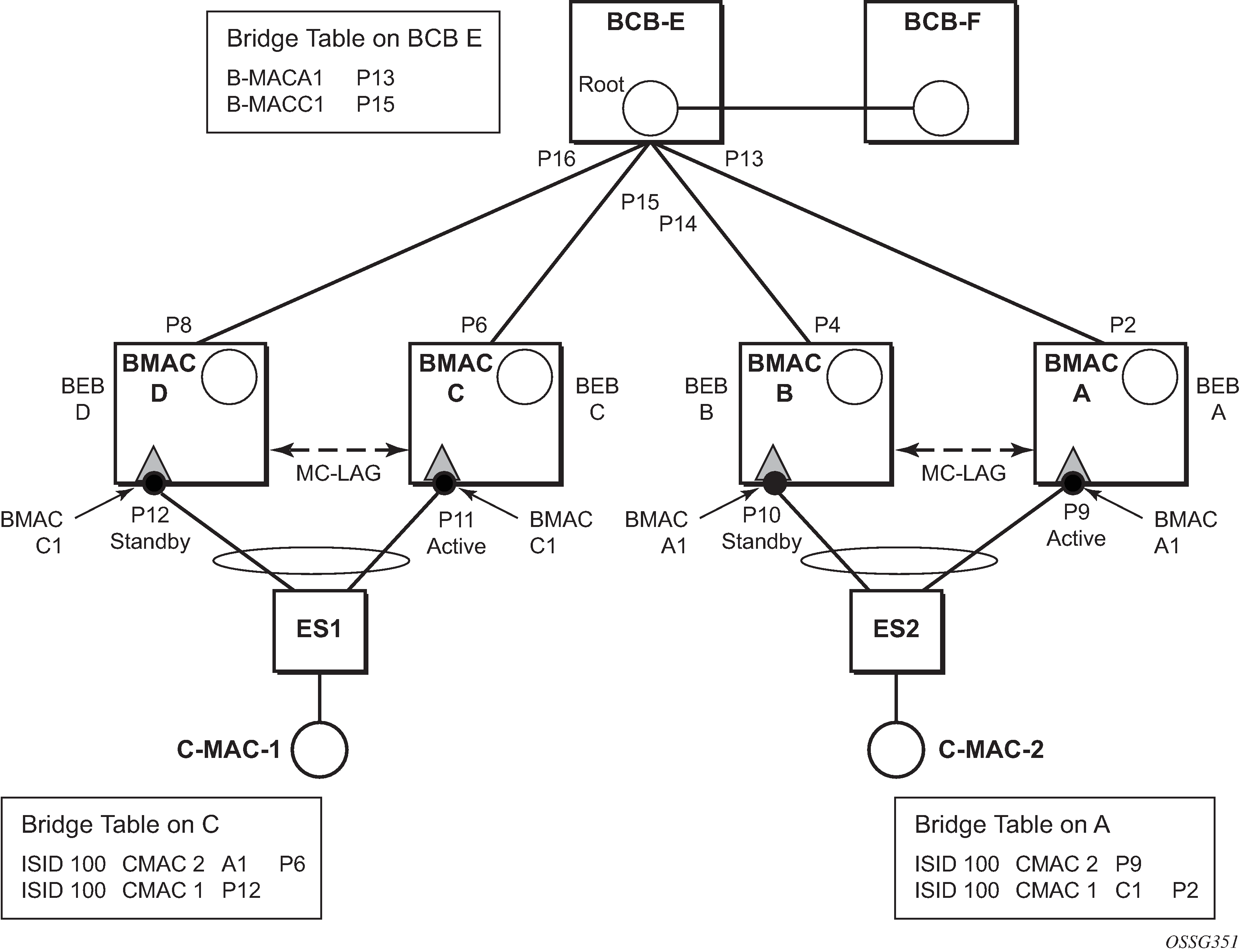
ES1 and ES2 are dual-homed using MC-LAG into two BEB devices: ES1 to BEB C and BEB D, ES2 to BEB A and BEB B. MC-LAG P11 on BEB C and P9 on BEB A are active on each side.
In the service context, the triangles are I-VPLS instances while the small circles are B-VPLS components with the related, per BVPLS source B-MACs indicated next to each BVPLS instances. P-MSTP or RSTP may be used for loop avoidance in the multi-point BVPLS. For simplicity, only the active SAPs (BEB P2, P4, P6 and P8) are shown in the diagram.
In addition to the source B-MAC associated with each BVPLS, there is an additional B-MAC associated with each MC-LAG supporting multihomed I-VPLS SAPs. The BEBs that are in a multihomed MC-LAG configuration share a common B-MAC on the related MC-LAG interfaces. For example, a common B-MAC C1 is associated in this example with ports P11 and P12 participating in the MC-LAG between BEB C and BEB D while B-MAC A1 is associated with ports P9 and P10 in the MC-LAG between BEB A and BEB B. While B-MAC C1 is associated through the I-VPLS SAPs with both BVPLS instances in BEB C and BEB D, it is actively used for forwarding to I-VPLS SAPs only on BEB C containing the active link P11.
MC-LAG protocol keeps track of which side (port or LAG) is active and which is standby for a specified MC-LAG grouping and activates the standby in case the active one fails. The source B-MAC C1 and A1 are used for PBB encapsulation as traffic arrives at the IVPLS SAPs on P11 and P9, respectively. MAC Learning in the BVPLS instances installs MAC FDB entries in BCB-E and BEB A as depicted in Figure: PBB active topology and access multihoming.
Active link (P11) or access node (BEB C) failures are activating through MC-LAG protocol the standby link (P12) participating in the MC-LAG on the pair MC-LAG device (BEB D).
Figure: Access multihoming - link failure shows the case of access link failure.
On failure of the active link P11 on BEB C the following processing steps apply:
-
MC-LAG protocol activates the standby link P12 on the pair BEB D.
-
B-MAC C1 becomes active on BEB D and any traffic received on BEB D with destination B-MAC C1 is forwarded on the corresponding I-VPLS SAPs on P12.
-
BEB D determines the related B-VPLS instances associated with all the I-VPLS SAPs mapped to P12, the newly activated MC-LAG links/LAG components.
-
Subsequently, BEB D floods in the related B-VPLS instances an Ethernet CFM-like message using C1 as source B-MAC. A vendor CFM opcode is used followed by an Nokia OUI.
-
As a result, all the FDB entries in BCBs or BEBs along the path are automatically updated to reflect the move of B-MAC C1 to BEB D.
In this particular configuration, the entries on BEB A do not need to be updated saving MAC Flush operation.
In other topologies, it is possible that the B-MAC C1 FDB entries in the B-VPLS instance on the remote BEBs (like BEB A) need to move between B-SAPs. This involves a move of all C-MAC using as next hop B-MAC C1 and the new egress line card.
An identical procedure is used when the whole BEB C fails.