This section discusses the access multihoming solution for PBB E-Line over an infrastructure of G.8031 Ethernet tunnels. Although a specific use case is used, the solution works the same for any other PBB infrastructure: for example, native PBB, pseudowire/MPLS, or a combination.
The PBB E-Line service and the related BVPLS infrastructure are depicted in Figure: Access multihoming solution for PBB Epipe.
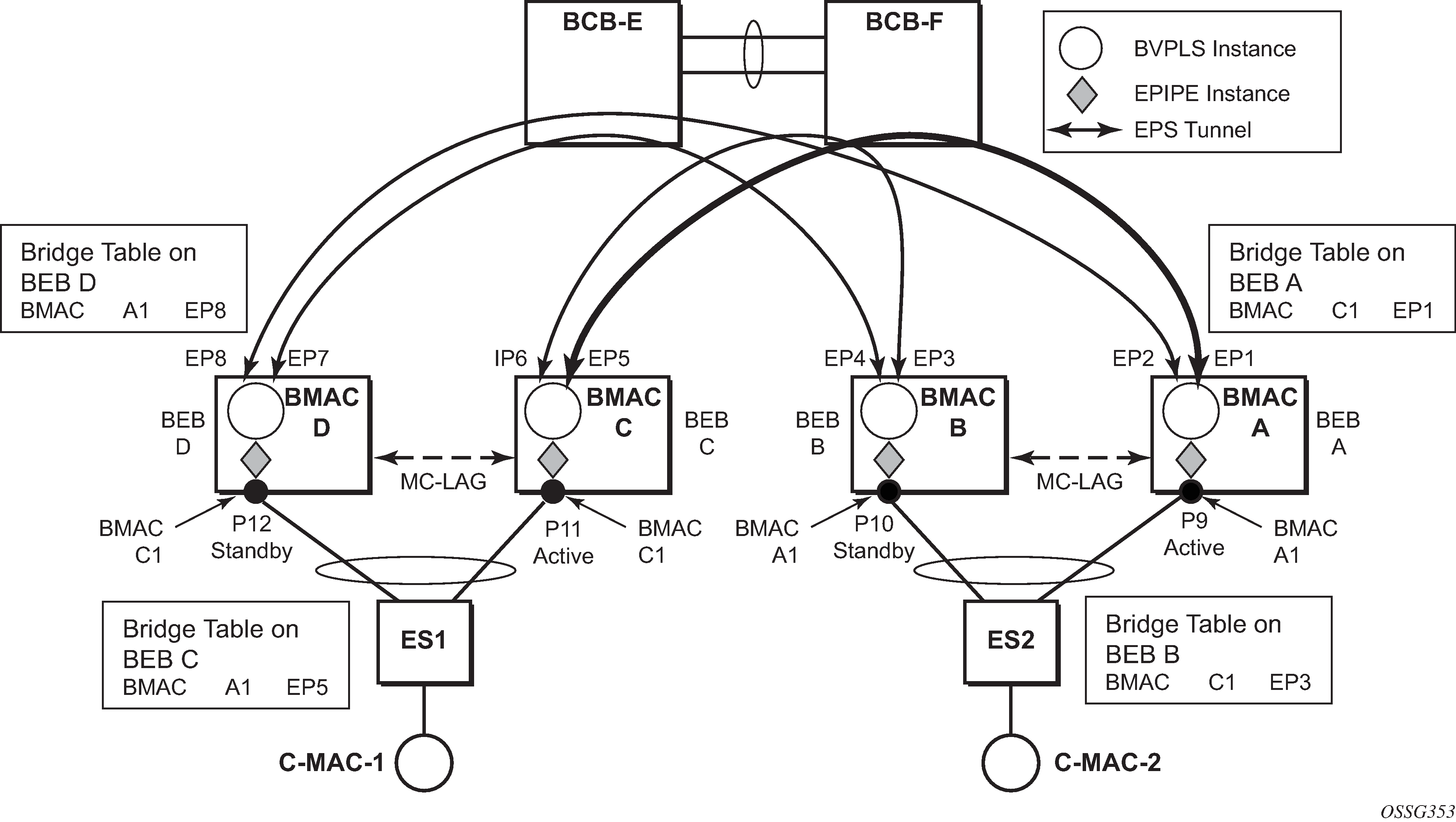
The E-Line instances are connected through the B-VPLS infrastructure. Each B-VPLS is interconnected to the BEBs in the remote pair using the G.8031, Ethernet Protection Switched (EPS) tunnels. Only the active Ethernet paths are shown in the network diagram to simplify the explanation. Split Horizon Groups may be used on EPS tunnels to avoid running MSTP/RSTP in the PBB core.
The same B-MAC addressing scheme is used as in the E-LAN case: a B-MAC per B-VPLS and additional B-MACs associated with each MC-LAG connected to an Epipe SAP. The B-MACs associated with the active MC-LAG are actively used for forwarding into B-VPLS the traffic ingressing related Epipe SAPs.
MC-LAG protocol keeps track of which side is active and which is standby for a specified MC-LAG grouping and activates the standby link in a failure scenario. The source B-MACs C1 and A1 are used for PBB encapsulation as traffic arrives at the Epipe SAPs on P11 and P9, respectively. MAC learning in the B-VPLS instances installs MAC FDB entries in BEB C and BEB A as depicted in Figure: Access multihoming solution for PBB Epipe. The highlighted Ethernet tunnel (EPS) is used to forward the traffic between BEB A and BEB C.
Active link (P11) or access node (BEB C) failures are activating through MC-LAG protocol, the standby link (P12) participating in the MC-LAG on the pair MC-LAG device (BEB D). The failure of BEB C is depicted in Figure: Access dual-homing for PBB E-Line - BEB failure. The same procedure applies for the link failure case.
The following process steps apply:
-
BEB D loses MC-LAG communication with its peer BEB C, no more keep alives from BEB C or next-hop tracking may kick in.
-
BEB D assumes BEB C is down and activates all shared MC-LAG links, including P12.
-
B-MAC C1 becomes active on BEB D and any traffic received on BEB C with destination B-MAC C1 is forwarded on the corresponding Epipe SAPs on P12.
-
BEB D determines the related B-VPLS instances associated with all the Epipe SAPs mapped to P12, the newly activated MC-LAG links/LAG components.
-
Subsequently, BEB D floods in the related B-VPLS instances the same Ethernet CFM message using C1 as source B-MAC.
-
As a result, the FDB entries in BEB A and BEB B are automatically updated to reflect the move of B-MAC C1 from EP1 to EP2 and from EP3 to EP4, respectively.
The same process is executed for all the MC-LAGs affected by BEB C failure so BEB failure can be the worst case scenario.