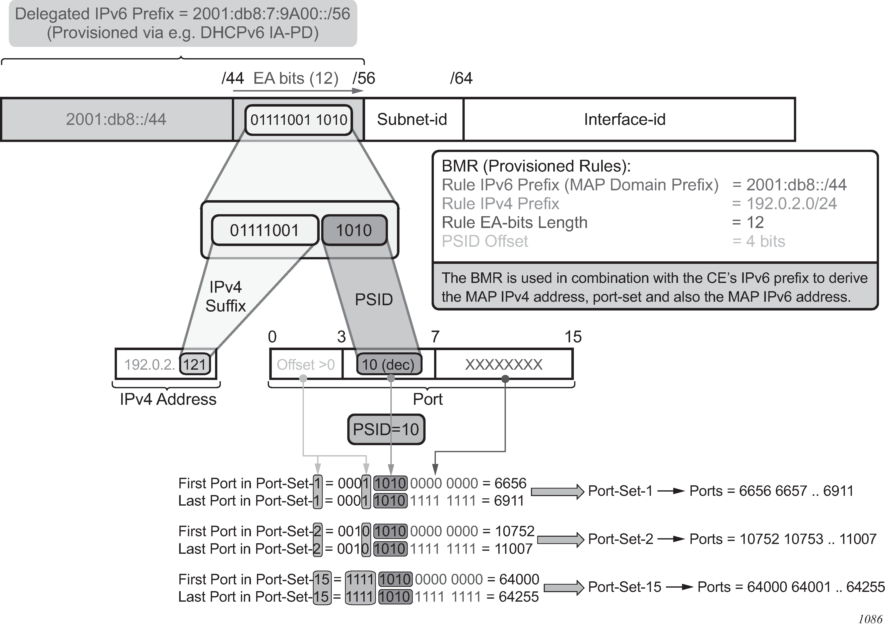
The public IPv4 address and the port-range information of the CE is encoded in its assigned IPv6 delegated prefix (IA-PD). The BMR holds the key to decode this information from the IA-PD of the CE. The BMR identifies the portion of bits of the IA-PD that contain the suffix of the IPv4 address and the port-set ID (PSID). These bits are called the EA bits. The PSID represents the port-range assigned to the CE.
The public IPv4 address of the CE is constructed by concatenating the IPv4 prefix carried in the BMR and the suffix, which is extracted from the EA bits within the IA-PD. The port-range is identified by the remaining EA bits (PSID portion). The EA bits uniquely identify the CE within the IPv6 network in a MAP domain.
The psid-offset value must be set to a value greater than 0. It represents ports that are omitted from the mapping (for example, well-known ports).
An IPv4 address and port on the private side of the CE must be statefully translated to a public IPv4 address, and the port within the assigned port must be set on the public side of the CE. This ensures that the BR, based on the same MAP rules, can extrapolate the IPv4 source of the packet for verification (anti-spoofing) purposes in the upstream direction, and conversely, to determine the destination IPv6 MAP address (CE address) in the downstream direction (based on the destination IPv4+port).
The IPv6 MAP address is constructed by setting the subnet-id in the delegated IPv6 prefix to 0. In this way, the subnet-id of 0 is reserved for MAP function. The remaining subnets can be delegated on the LAN side of the CE.
The interface-id is set to the IPv4 public address and PSID. This is described in RFC 7599, §6.
In this way, the IPv4 and IPv6 addresses of the CE are defined and easily converted to each other based on the BMR and the port information in the packet. Figure: A+P mapping shows the A+P mapping algorithm.