TI-LFA node-protect operation

About this task

The SRĀ OS supports the node-protect extensions to the TI-LFA algorithm as described in draft-bashandy-rtgwg-segment-routing-ti-lfa-05.

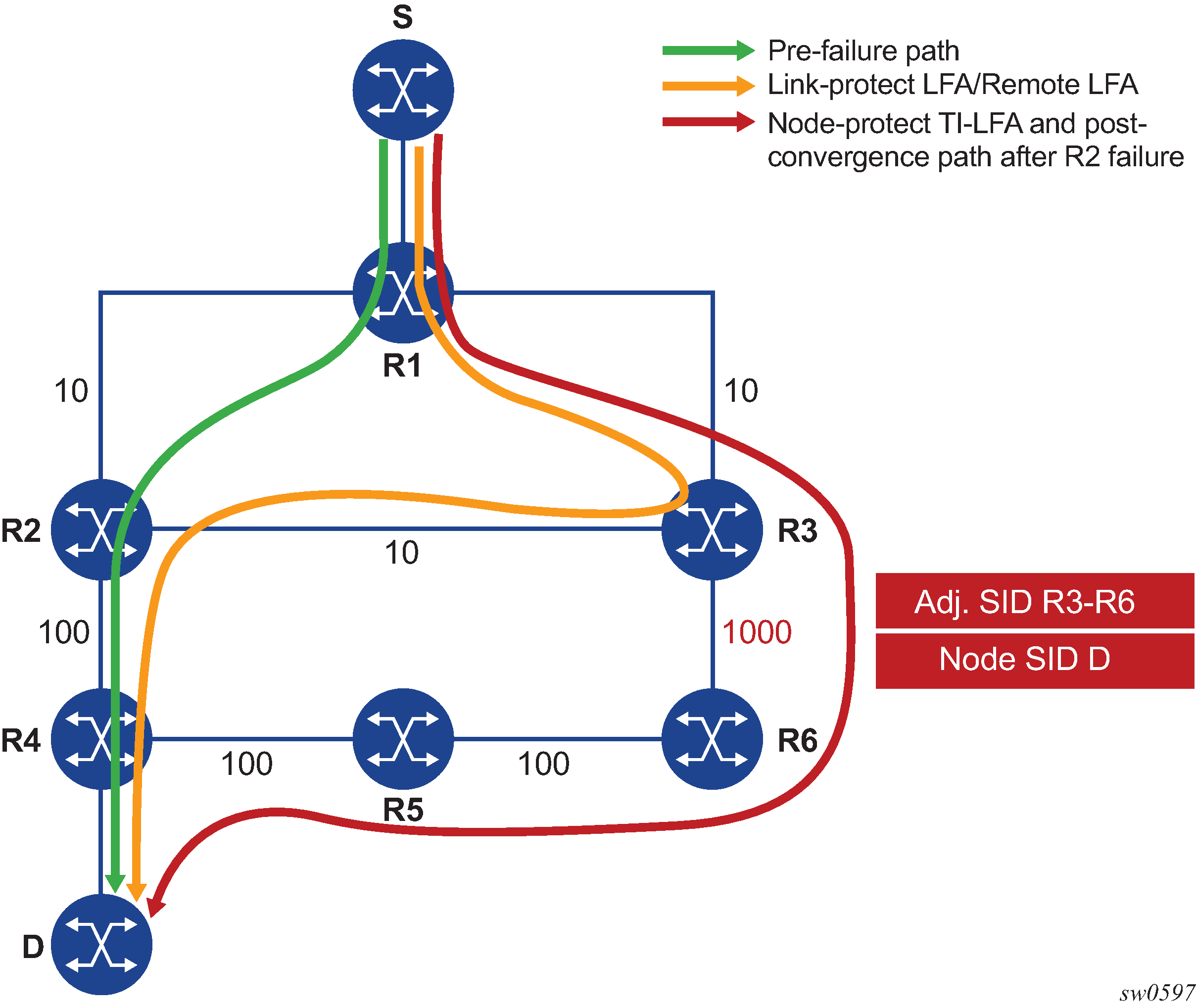
Figure: Application of the TI-LFA algorithm for node protection shows a simple topology to illustrate the operation of the node-protect in the TI-LFA algorithm.

Figure: Application of the TI-LFA algorithm for node protection

The first change is that the algorithm has to protect a node instead of a link.

The following topology computations pertain to Figure: Application of the TI-LFA algorithm for node protection:

For each destination prefix D, R1 programs the TI-LFA repair tunnel (max-sr-frr-labels=1):

Procedure

  1. Compute post-convergence SPF on the topology without the protected node.

    In Figure: Application of the TI-LFA algorithm for node protection, R1 computes TI-LFA on the topology without the protected node R2 and finds a single post-convergence path to destination D via R3 and R6.

    Prefixes owned by all other nodes in the topology have a post-convergence path via R3 and R6 except for prefixes owned by node R2. The latter uses the link R3-R2 and they can only benefit from link protection.

  2. Compute extended P-Space of R1 with respect to protected node R2 on the post-convergence paths.

    This is the set of nodes Yi in the post-convergence paths that are reachable from R1 neighbors, other than protected node R2, without any path transiting the protected node R2.

    R1 computes an LFA SPF rooted at each of its neighbors within the post-convergence paths, for example, R3, using the following equation:

    Distance_opt(R3, Yi) < Distance_opt(R3, R2) + Distance_opt(R2, Yi)

    Where:

    Distance_opt(A,B) is the shortest distance between A and B.

    The extended P-space calculation yields node R3 only.

  3. Compute Q-space of R1 with respect to protected link R1-R2 on the post-convergence paths.

    This is the set of nodes Zi in the post-convergence paths from which node R2 can be reached without any path transiting the protected link R1-R2.

    Distance_opt(Zi, R2) < Distance_opt(Zi, R1) + Distance_opt(R1, R2)

    The reverse SPF for the Q-space calculation is the same as in the link-protect algorithm and uses the protected node R2 as the proxy for all destination prefixes. Note that if the Q-space were to be computed with respect to the protected node R2 instead of link R1-R2, a reverse SPF would have to be done to each destination D which is very costly and would not scale. Computing Q-space with respect to link R1-R2 however means the algorithm only guarantees the path from the computing node to the Q node is node-protecting. The path from the Q node to the destination Dis not guaranteed to avoid the protected node R2. The intersection of the Q-space with post-convergence path is modified in the next step to mitigate this risk.

    This step yields nodes R3, R4, R5, and R6.

  4. For each post-convergence path, search for the closest Q-node to destination D and select the closest P-node to this Q-node, up to a number of labels corresponding to the value of ti-lfa max-sr-frr-labels labels.

    This step yields the following P-Q sets depending on the value of the parameter max-sr-frr-labels:

    • max-sr-frr-labels=0, R3 is the closest Q node to the destination D and R3 is the only P node. This case is the one which results in link protection via PQ node R3.

    • max-sr-frr-labels=1, R6 is the closest Q node to the destination D and R3 is the only P node. The repair tunnel for this case uses the SID of the adjacency over link R3-R6 and is illustrated in Figure: Application of the TI-LFA algorithm for node protection.

    • max-sr-frr-labels=2, R5 is the closest Q node to the destination D and R3 is the only P node. The repair tunnel for this case uses the SIDs of the adjacencies over links R3-R6 and R6-R5.

    • max-sr-frr-labels=3, R4 is the closest Q node to the destination D and R3 is the only P node. The repair tunnel for this case uses the SIDs of the adjacencies over links R3-R6, R6-R5, and R5-R4.

    Note this step of the algorithm is modified from link protection which prefers Q nodes which are the closest to the computing router R1. This is to minimize the probability that the path from the Q node to the destination D goes via the protected node R2 as described in step 2. There is however still a probability that the found P-Q set achieves link protection only.

  5. Select the P-Q Set.

    If a candidate P-Q set is found on each of the multiple ECMP post-convergence paths in step 4, the following selection rules are applied in ascending order to select a single set:

    1. lowest number of labels

    2. lowest next-hop router ID

    3. lowest interface index if same next-hop router ID

    If multiple parallel links with adjacency SID exist between the P and Q nodes of the selected P-Q set, the following rules are used to select one of them:

    • Adjacency SID with lowest metric

    • Adjacency SID with the lowest SID value if same lowest metric