Precision Time Protocol (PTP) is only supported on the 7210 SAS-D ETR, 7210 SAS-Dxp 12p ETR, 7210 SAS-Dxp 16p, 7210 SAS-Dxp 24p, 7210 SAS-K 2F1C2T, 7210 SAS-K 2F6C4T, and 7210 SAS-K 3SFP+ 8C.
References to G.8275.1 and Ethernet encapsulation apply only to the 7210 SAS-Dxp 12p ETR, 7210 SAS-K 2F6C4T, and 7210 SAS-K 3SFP+ 8C.
PTP is a timing-over-packet protocol defined in the IEEE 1588v2 standard 1588 PTP 2008.
PTP may be deployed as an alternative timing-over-packet option to ACR. PTP provides the capability to synchronize network elements to a Stratum-1 clock or primary reference clock (PRC) traceable source over a network that may or may not be PTP-aware. PTP has several advantages over ACR. It is a standards-based protocol, has lower bandwidth requirements, can transport both frequency and time, and can potentially provide better performance.
The following is a list of the four basic types of PTP devices:
ordinary clock
boundary clock
end-to-end transparent clock
peer-to-peer transparent clock
See Synchronization options available on 7210 SAS platforms for more information about supported PTP device types on 7210 SAS platforms.
Figure: Peer clocks shows how the 7210 SAS communicates with peer 1588v2 clocks. These peers can be ordinary clock timeReceivers or boundary clocks. The communication can be based on either unicast IPv4 sessions transported through IP interfaces or Ethernet multicast PTP packets transported through an Ethernet port.
The following table describes IP/UDP unicast and multicast support for the 7210 SAS platforms.
Protocol |
IP/UDP unicast |
Ethernet multicast |
|---|---|---|
7210 SAS-D |
Yes1 |
No |
7210 SAS-Dxp 12p |
No |
Yes1 |
7210 SAS-Dxp 16p |
No |
Yes |
7210 SAS-Dxp 24p |
No |
Yes |
7210 SAS-K 2F1C2T |
Yes |
No |
7210 SAS-K 2F6C4T |
Yes |
Yes |
7210 SAS-K 3SFP+ 8C |
Yes |
Yes |
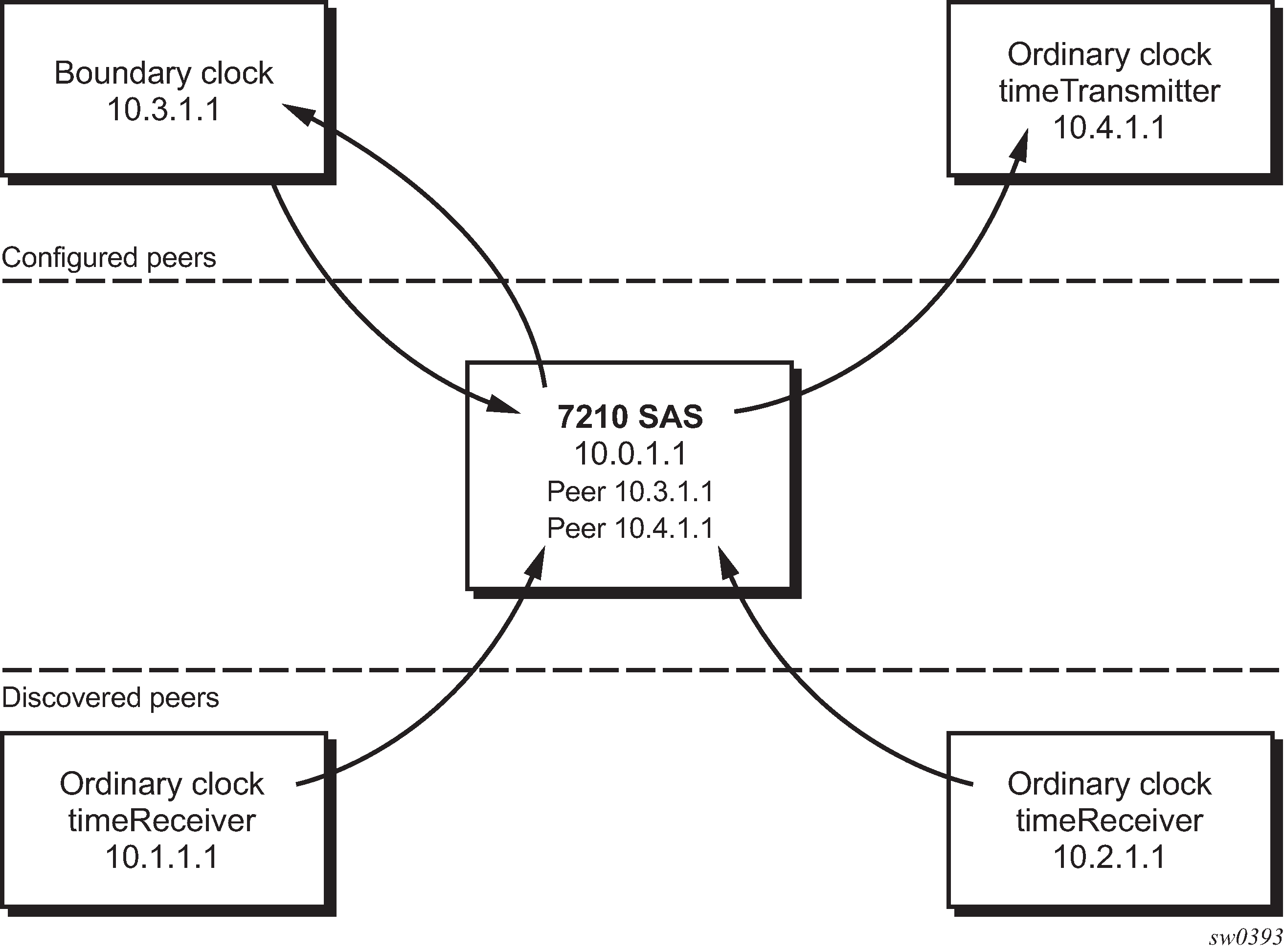
Unicast IP sessions support two types of peers: configured and discovered. The 7210 SAS operating as an ordinary clock timeReceiver or as a boundary clock must have configured peers for each PTP neighbor clock from which it may accept synchronization information. The 7210 SAS initiates unicast sessions with all configured peers. A 7210 SAS operating as a boundary clock accepts unicast session requests from external peers. If the peer is not configured, it is considered a discovered peer. The 7210 SAS can deliver synchronization information toward discovered peers (that is, timeReceivers).
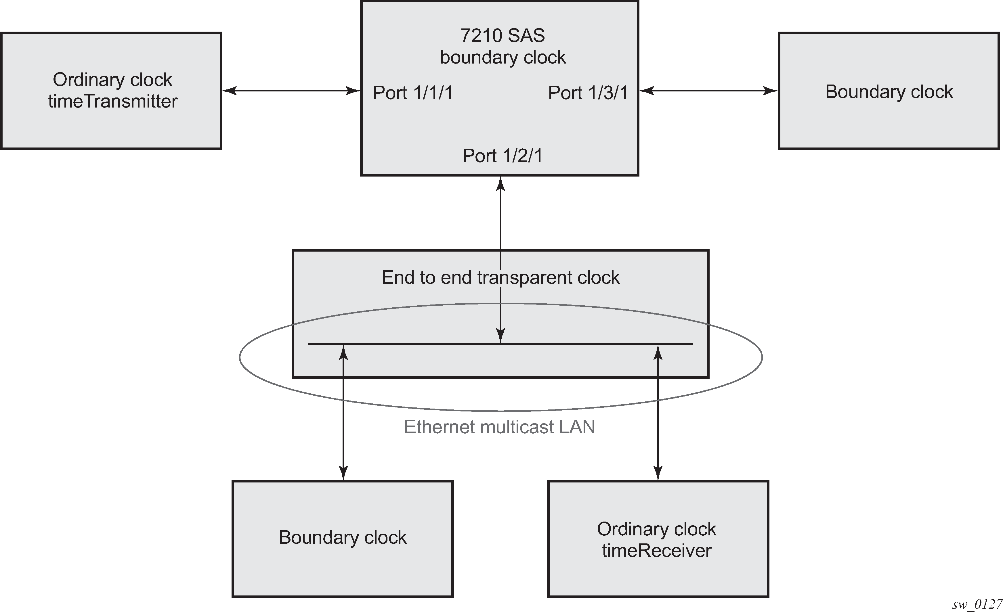
For Ethernet multicast operation, the node listens for and transmits PTP messages using the configured multicast MAC address. Neighbor clocks are discovered via messages received through an enabled Ethernet port. Figure: Ethernet multicast ports shows how the 7210 SAS supports only one neighbor PTP clock connecting into a single port.
The 7210 SAS does not allow for simultaneous PTP operations using both unicast IPv4 and Ethernet multicast. A change of profile to G.8275.1 or from G.8275.1 to another profile requires a reboot of the node.
The following figure shows the relationship of various neighbor clocks using unicast IP sessions to communicate with a 7210 SAS configured as a boundary clock with two configured peers.
The following figure shows the relationship of various neighbor clocks using multicast Ethernet sessions to a 7210 SAS configured as a boundary clock.
7210 SAS platforms do not support the ordinary clock timeTransmitter configuration.
The IEEE 1588v2 standard includes the concept of PTP profiles. These profiles are defined by industry groups or standards bodies that define the use of IEEE 1588v2 for specific applications.
The 7210 SAS currently supports three profiles. The following table lists PTP profile support for 7210 SAS platforms.
PTP profiles |
7210 SAS platforms |
||||||
|---|---|---|---|---|---|---|---|
|
7210 SAS-D ETR |
7210 SAS-Dxp 12p ETR |
7210 SAS-Dxp 16p |
7210 SAS-Dxp 24p |
7210 SAS-K 2F1C2T |
7210 SAS-K 2F6C4T |
7210 SAS-K 3SFP+ 8C |
|
IEEE 1588v2 (default profile) |
✓ |
✓ |
✓ |
✓ |
|||
ITU-T Telecom profile (G.82651) |
✓ |
✓ |
✓ |
✓ |
|||
|
ITU-T Telecom profile for time with full timing support (G.8275.1) |
✓ |
✓ |
✓ |
||||
| IEC/IEEE 61850-9-3 and C37.238-2017 profiles | ✓ | ✓ | |||||
When a 7210 SAS receives Announce messages from one or more configured peers or multicast neighbors, it executes a Best timeTransmitter Clock Algorithm (BTCA) to determine the state of communication between itself and the peers. The system uses the BTCA to create a hierarchical topology, allowing the flow of synchronization information from the best source (the grandmaster clock) out through the network to all boundary and timeReceiver clocks. Each profile has a dedicated BTCA.
If the profile setting for the clock is ieee1588-2008, the precedence order for the BTCA is as follows:
priority1
clock class
clock accuracy
PTP variance (offsetScaledLogVariance)
priority2
clock identity
steps removed from the grandmaster
The following table describes how the 7210 SAS sets its local parameters.
Parameter |
Value |
|---|---|
clockClass |
248 - the 7210 SAS is configured as a boundary clock 255 - the 7210 SAS is configured as an ordinary clock timeReceiver |
clockAccuracy |
FE - unknown |
offsetScaledLogVariance |
FFFF - not computed |
clockIdentity |
Chassis MAC address following the guidelines of section 7.5.2.2.2 of IEEE 1588-2008 |
If the profile setting for the clock is itu-telecom-freq (ITU G.8265.1 profile), the precedence order for the best timeTransmitter selection algorithm is the following:
clock class
PTSF (Packet Timing Signal Fail) - Announce Loss (miss 3 Announce messages or do not get an Announce message for 6 seconds)
priority
The following table describes how the 7210 SAS sets its local parameters.
Parameter |
Value |
|---|---|
clockClass |
80-110 - value corresponding to the QL out of the central clock of the 7210 SAS as per Table 1/G.8265.1 255 - the 7210 SAS is configured as an ordinary clock timeReceiver |
The ITU-T profile is for use in environments with only ordinary clock timeTransmitters and timeReceivers for frequency distribution.
If the profile setting for the clock is g8275dot1-2014, the precedence order for the best timeTransmitter selection algorithm is very similar to that used for the default profile. It ignores the priority1 parameter, includes a localPriority parameter, and includes the ability to force a port to never enter the timeReceiver state (master-only). The precedence is as follows:
clock class
clock accuracy
PTP variance (offsetScaledLogVariance)
priority2
localPriority
clock identity
steps removed from the grandmaster
The following table describes how the 7210 SAS sets its local parameters.
Parameter |
Value |
|---|---|
clockClass |
165 - the 7210 SAS is configured as a boundary clock and the boundary clock was previously locked to a grandmaster with a clock class of 6 248 - the 7210 SAS is configured as a boundary clock 255 - the 7210 SAS is configured as an ordinary clock timeReceiver |
clockAccuracy |
FE - unknown |
offsetScaledLogVariance |
FFFF - not computed |
clockIdentity |
Chassis MAC address following the guidelines of section 7.5.2.2.2 of IEEE 1588-2008 |
The 7210 SAS can support a limited number of configured peers (possible timeTransmitter or neighbor boundary clocks) and a limited number of discovered peers (timeReceivers).These peers use the unicast negotiation procedures to request service from the 7210 SAS clock. A neighbor boundary clock counts for two peers (both a configured and a discovered peer) toward the maximum limit.
On the 7210 SAS-D ETR, 7210 SAS-Dxp 12p ETR, 7210 SAS-K 2F1C2T, 7210 SAS-K 2F6C4T, and 7210 SAS-K 3SFP+ 8C, there are limits on the number of timeReceivers enforced in the implementation for unicast and multicast PTP timeReceivers. Contact your Nokia technical support representative for information about the specific unicast message limits related to PTP.
When PTP is configured, the PTP load must be monitored to ensure that the load does not exceed the capabilities (configured values) to ensure that sufficient CPU processing cycles are available for PTP. There are several commands that can be used for this monitoring, including show system cpu, which identifies the load of the PTP software process. If the ‟capacity usage” reaches 100%, the PTP software process on the 7210 SAS is at its limit of transmitting or receiving PTP packets.
Because the user cannot control the number of PTP messages received by the 7210 SAS over its Ethernet ports, the following statistics commands can be used to identify the source of the message load:
show system ptp statistics displays aggregate packet rates
show system ptp port and show system ptp port port-id [detail] display received packet rates
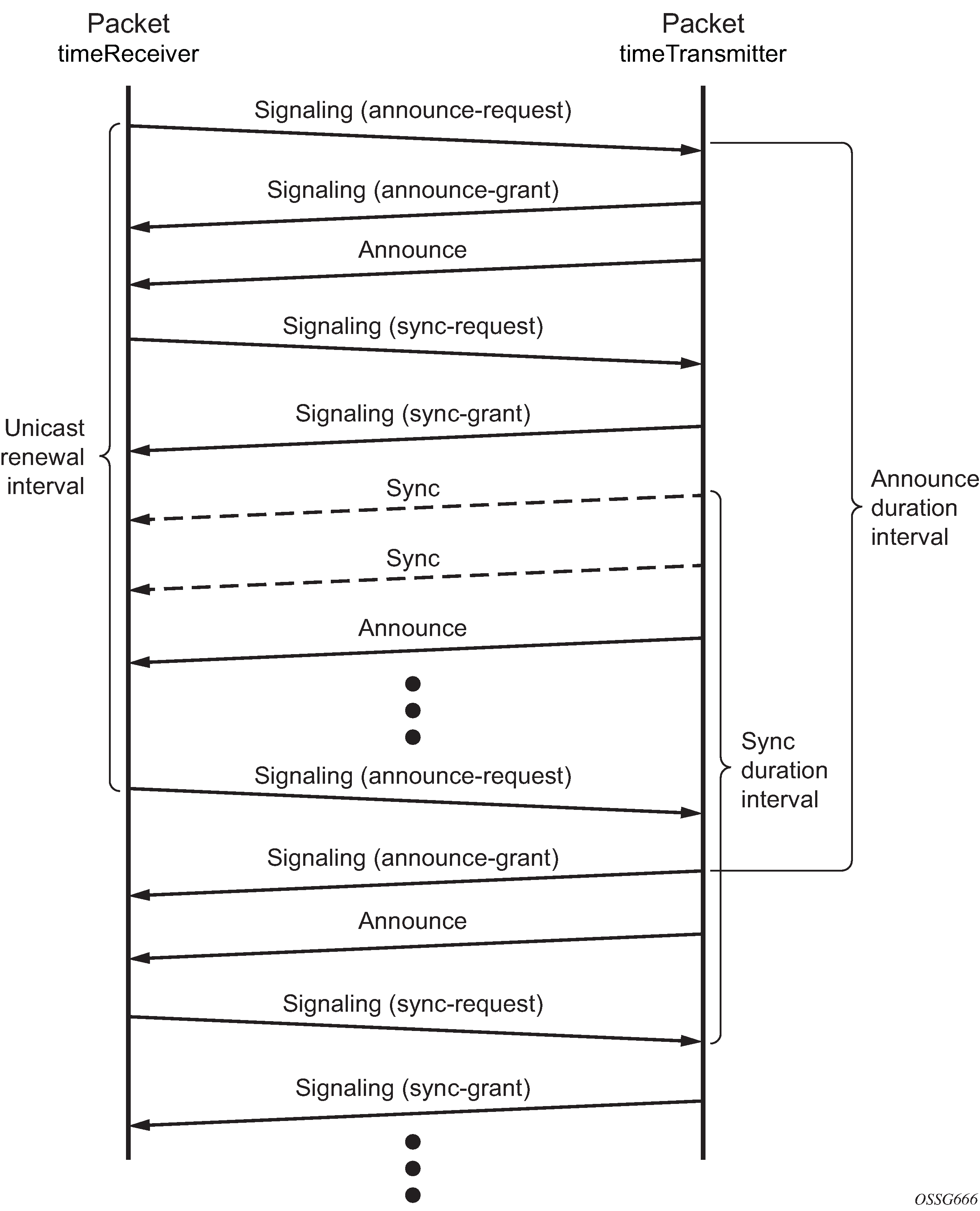
The following figure shows the unicast negotiation procedure performed between a timeReceiver and a peer clock that is selected to be the timeTransmitter clock. The timeReceiver clock will request Announce messages from all peer clocks but only request Sync and Delay_Resp messages from the clock selected to be the timeTransmitter clock.