Figure: BIER forwarding shows that IGP builds the BIFT using IGP BIER TLVs. Each node also builds its LTN table based on IGP-advertised MPLS labels.
The BIER routing table is constructed based on the combination of:
Set ID (SI)
BIER String Length (BSL)
Sub Domain (SD)
This information is presented as <SD, BSL, SI>. An MPLS label is assigned locally for each BIER routing table and is advertised using IGP to peers.
For example, if there are 512 PEs and the BSL is 256 there are two forwarding tables with each table having its own label as follows:
<SD=0, BSL=256, SI=0> represented with a unique local label
<SD=0, BSL = 256, SI=1> represented with a second unique local label
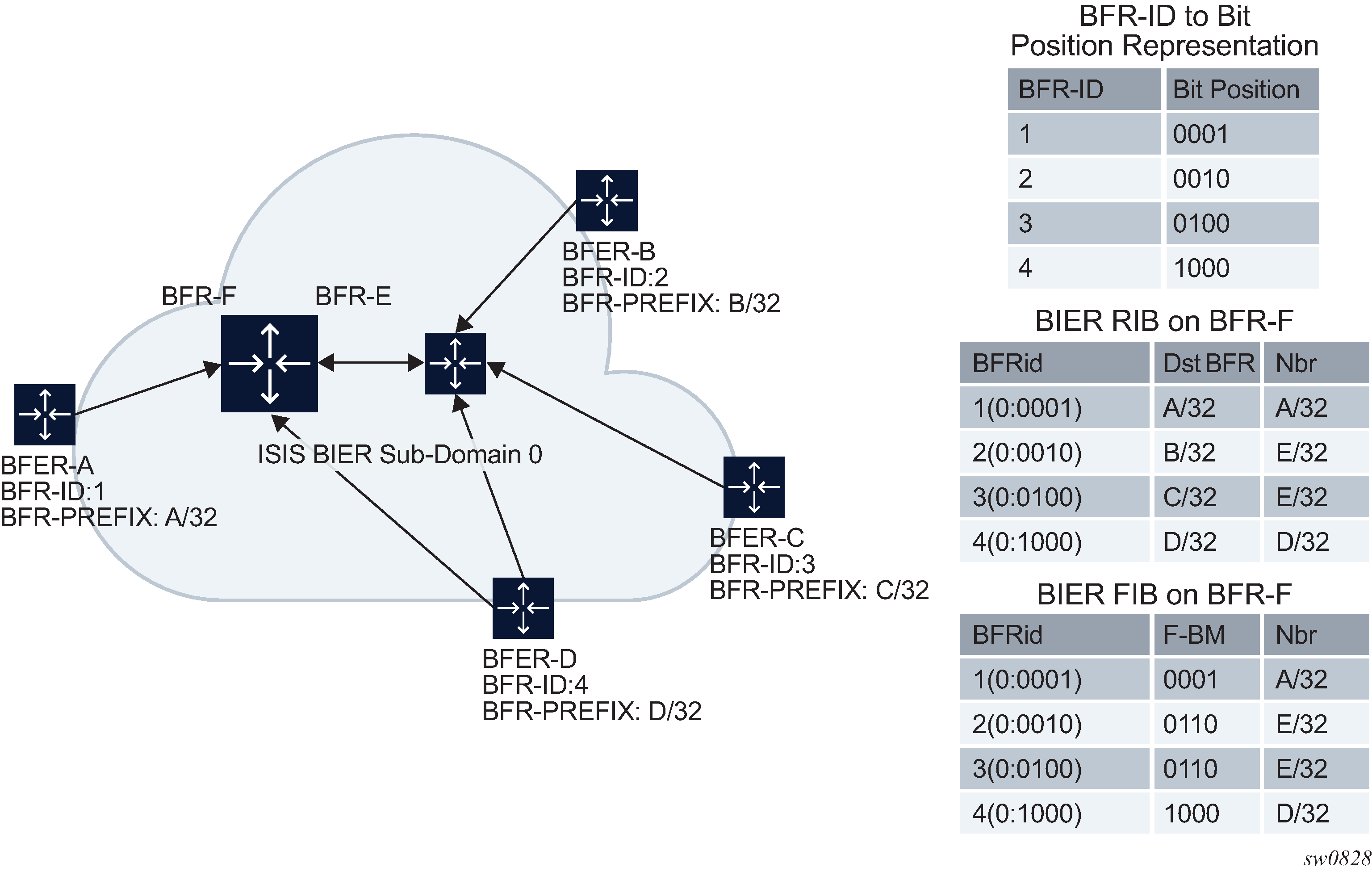
Each node is presented in the BIER header using its BFR-ID. It is recommended to assign the BFR-IDs sequentially and in a tight order for the PEs so that no bits in the BIER header remain unused.
After all BFRs forward their BIER information using IGP BIER TLV, each BFR builds its own BIER RIB and BIER FIB. In the Figure: BIER forwarding example, PE A is represented using BFR-ID 1 (0:0001) and PE B is represented using BFR-ID 2 (0:0010) and so on. Therefore, on BFR F, the routing table is built based on this information. In the Figure: BIER forwarding example, BFR A (0:0001) has a destination of A/32 and its neighbor also has a destination of A/32 because of it directly being attached to BFR F. BFR B (0:0010) has destination of B/32 but is reachable using BFR E.
Therefore, the routing table for each PE is built based on its BFR-ID, destination IP address and the direct neighbor which it is attached.
The FIB is built based on the summation of the routes in the RIB that have the same neighbor. In the Figure: BIER forwarding example, BFER B and C have the same neighbor/peer BFR E. As a result, their FIB entry is identical BFR-ID 2 (0:0010) Forwarding bit mask 0110 neighbor/peer E/32; where the forwarding bit mask is a summation of BFR-ID nodes B and C (bit 2 and 3).