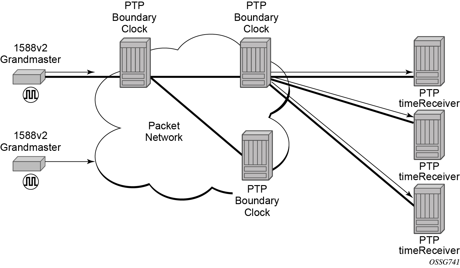
The router supports boundary clock PTP devices in both timeTransmitter and timeReceiver states. IEEE 1588v2 can function across a packet network that is not PTP-aware; however, the performance may be unsatisfactory and unpredictable. PDV across the packet network varies with the number of hops, link speeds, utilization rates, and the inherent behavior of the routers. By using routers with boundary clock functionality in the path between the grandmaster clock and the timeReceiver clock, one long path over many hops is split into multiple shorter segments, allowing better PDV control and improved timeReceiver performance. This allows PTP to function as a valid timing option in more network deployments and allows for better scalability and increased robustness in various topologies, such as rings. Boundary clocks can simultaneously function as a PTP timeReceiver of an upstream grandmaster (ordinary clock) or boundary clock, and as a PTP timeTransmitter of downstream timeReceivers (ordinary clock) and boundary clocks, as shown in Figure: Boundary clock.
In addition, the use of port-based timestamping in every network element between the grandmaster and the end timeReceiver application is highly recommended for delivering time to meet one microsecond accuracies required of mobile applications.
The router always uses the frequency output of the central clock to maintain the timebase within the router. The PTP reference into the central clock should always be enabled as an option if the router is configured as a boundary clock. This avoids the situation of the router entering holdover while propagating time with 1588.