Precision Time Protocol (PTP) is a timing-over-packet protocol defined in the IEEE 1588v2 standard 1588 PTP 2008.
PTP may be deployed as an alternative timing-over-packet option to Adaptive Clock Recovery (ACR). PTP provides the capability to synchronize network elements to a Stratum-1 clock or primary reference clock (PRC) traceable frequency source over a network that may or may not be PTP-aware. PTP has several advantages over ACR. It is a standards-based protocol, has lower bandwidth requirements, can transport both frequency and time, and can potentially provide better performance.
Support is provided for an ordinary clock in timeReceiver or timeTransmitter mode or a boundary clock. When configured as an ordinary clock timeTransmitter, PTP can only be used for the distribution of a frequency reference, not a time reference. The boundary clock and ordinary clock timeReceiver can be used for both frequency and time distribution.
The ordinary clock timeTransmitter, ordinary clock timeReceiver, and boundary clock communicate with neighboring IEEE 1588v2 clocks. These neighbor clocks can be ordinary clock timeTransmitters, ordinary clock timeReceivers, or boundary clocks. The communication can be based on either unicast IPv4 sessions transported through IP interfaces or multicast Ethernet transported through Ethernet ports.
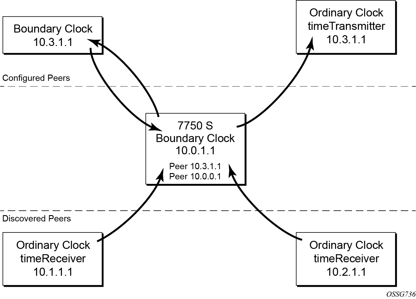
For the unicast IP sessions, the external clocks are labeled 'peers'. There are two types of peers: configured and discovered. An ordinary clock timeReceiver or a boundary clock should have configured peers for each PTP neighbor clock from which it may accept synchronization information. The router initiates unicast sessions with all configured peers. An ordinary clock timeTransmitter or boundary clock accepts unicast session requests from external peers. If the peer is not a configured peer, then it is considered a discovered peer. An ordinary clock timeTransmitter or boundary clock can deliver synchronization information toward discovered peers. Figure: Peer clocks shows the relationship of various neighbor clocks using unicast IP sessions to communicate with a 7750 SR configured as a boundary clock with two configured peers.
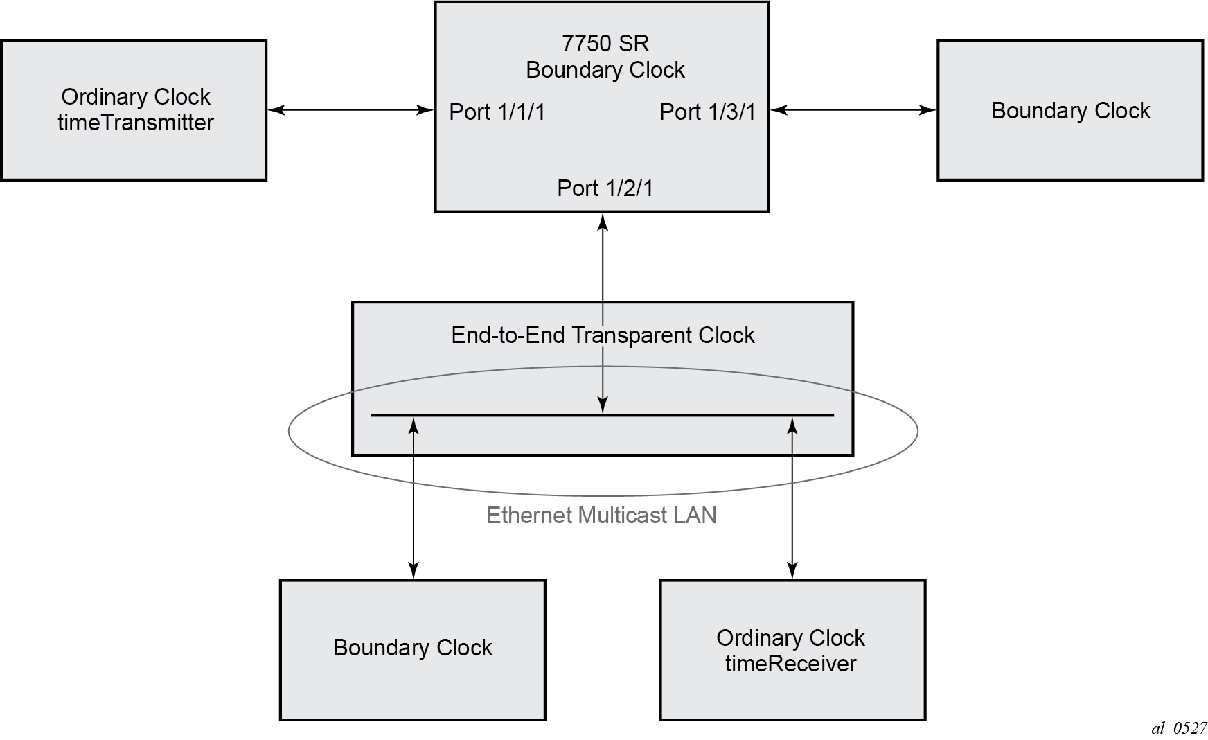
For multicast Ethernet operation, the router listens for and transmit PTP messages using the configured multicast MAC address. Neighbor clocks are discovered via the reception of messages through an enabled Ethernet port. An ordinary clock timeTransmitter, ordinary clock timeReceiver, and a boundary clock support more than one neighbor PTP clock connecting into a single port. This may be encountered with the deployment of an Ethernet multicast LAN segment between the local clock and the neighbor PTP ports using an end-to-end transparent clock or an Ethernet switch. The Ethernet switch is not recommended because of the introduction of PDV and the potential degradation of performance but it can be used if appropriate to the application. Figure: Ethernet multicast ports shows the relationship of various neighbor clocks using multicast Ethernet sessions to a 7750 SR configured as a boundary clock. The 7750 SR has three ports configured for multicast Ethernet communications. Port 1/2/1 of the 7750 SR shows a connection where there are two neighbor clocks connecting to one port of the 7750 SR through an end-to-end transparent clock.
The ordinary clock timeTransmitter, ordinary clock timeReceiver, and boundary clock allow for PTP operation over both unicast IPv4 and multicast Ethernet at the same time.
The IEEE 1588v2 standard includes the concept of PTP profiles. These profiles are defined by industry groups or standards bodies that define how IEEE 1588v2 is to be used for a particular application.
Currently, three profiles are supported:
IEEE 1588v2 default profile
ITU-T Telecom profile for frequency (G.8265.1)
ITU-T Telecom profile for time with full timing support (G.8275.1)
When an ordinary clock timeReceiver or a boundary clock receive Announce messages from one or more configured peers or multicast neighbors, it executes a Best TimeTransmitter Clock Algorithm (BTCA) to determine the state of communication between itself and the peers. The system uses the BTCA to create a hierarchical topology allowing the flow of synchronization information from the best source (the grandmaster clock) out through the network to all boundary and timeReceiver clocks. Each profile has a dedicated BTCA.
If the profile setting for the clock is ieee1588-2008, the precedence order for the BTCA is as follows:
-
priority1
-
clockClass
-
clockAccuracy
-
PTP variance (offsetScaledLogVariance)
-
priority2
-
clockIdentity
-
stepsRemoved from the grandmaster
The ordinary clock timeTransmitter, ordinary clock timeReceiver, and boundary clock set their local parameters as listed in Table: Local clock parameters when profile is set to ieee1588-2008:
| Parameter | Value |
|---|---|
clockIdentity |
Chassis MAC address following the guidelines of 7.5.2.2.2 of IEEE 1588 |
clockClass |
13 — local clock configured as ordinary clock timeTransmitter and is locked to an external reference 14 — local clock configured as ordinary clock timeTransmitter and in holdover after having been locked to an external source 248 — local clock configured as ordinary clock timeTransmitter and is in free run or the router is configured as a boundary clock 255 — local clock configured as ordinary clock timeReceiver |
clockAccuracy |
FE — unknown |
offsetScaledLogVariance |
FFFF — not computed |
If the profile setting for the clock is g8265dot1-2010, the precedence order for the best timeTransmitter selection algorithm is:
-
clockClass
-
priority
The ordinary clock timeTransmitter, ordinary clock timeReceiver, and boundary clock set their local parameters as listed in Table: Local clock parameters when profile is set to itu-telecom-freq:
| Parameter | Value |
|---|---|
clockClass |
80-110 — value corresponding to the QL out of the central clock as per Table 1/G.8265.1 255 — the clock is configured as ordinary clock timeReceiver |
The g8265dot1-2010 profile is for use in an environment with only ordinary clock timeTransmitters and timeReceivers for frequency distribution.
If the profile setting for the clock is g8275dot1-2014, the precedence order for the best timeTransmitter selection algorithm is very similar to that used with the default profile. It ignores the priority1 parameter, includes a localPriority parameter and includes the ability to force a port to never enter timeReceiver state (timeTransmitter-only). The precedence is as follows:
-
clockClass
-
clockAccuracy
-
PTP variance (offsetScaledLogVariance)
-
priority2
-
localPriority
-
clockIdentity (See Note)
-
stepsRemoved from the grandmaster
The ordinary clock timeTransmitter, ordinary clock timeReceiver, and boundary clock set their local parameters as listed in Table: Local clock parameters when profile is set to g8275dot1-2014:
| Parameter | Value |
|---|---|
clockIdentity |
Chassis MAC address following the guidelines of 7.5.2.2.2 of IEEE 1588 |
clockClass |
165 — local clock configured to a boundary clock and the boundary clock was previously locked to a grandmaster with a clock class of 6 248 — local clock configured as boundary clock 255 — local clock configured as ordinary clock timeReceiver |
clockAccuracy |
FE — unknown |
offsetScaledLogVariance |
FFFF — not computed |
There is a limit on the number of external PTP clocks to which the ordinary clock timeReceiver or boundary clock requests unicast service (number of configured peers) and also a limit to the number of external PTP clocks to which the ordinary clock timeTransmitter or boundary clock grants unicast service (number of discovered peers). An association where the boundary clock has a symmetric relationship with another boundary clock (in other words, they both have the other as a configured peer) consumes a request and a grant unicast service in each router.
The number of configured Ethernet ports is not restricted.
There are limits to the maximum transmitted and received event message rates supported in the router. Each unicast IP service established consumes a portion of one of the unicast message limits. When either limit is reached, additional unicast service requests are refused by sending a grant response with zero in the duration field.
See the scaling guide for the appropriate release for the specific unicast message limits related to PTP.
Multicast messages are not considered when validating the unicast message limit. When multicast messaging on Ethernet ports is enabled, the PTP load needs to be monitored to ensure the load does not exceed the capabilities. There are several commands that can be used for this monitoring
The show system cpu command identifies the load of the PTP software process. If the capacity usage reaches 100%, the PTP software process on the router is at its limit of transmitting and receiving PTP packets.
Because the user cannot control the amount of PTP messages being received over the Ethernet ports, the statistics commands can be used to identify the source of the message load:
show system ptp statistics has aggregate packet rates
show system ptp port and show system ptp port port-id [detail] display received packet rates
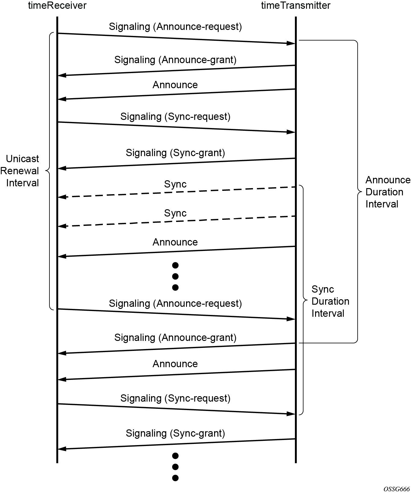
Figure: Messaging sequence between the PTP timeReceiver clock and PTP timeTransmitter clock shows the unicast negotiation procedure performed between a timeReceiver and a peer clock that is selected to be the timeTransmitter clock. The timeReceiver clock requests Announce messages from all peer clocks but only request Sync and Delay_Resp messages from the clock selected to be the timeTransmitter clock.