The IEEE 1588v2 standard allows for synchronization of the frequency and time from a timeTransmitter clock to one or more timeReceiver clocks over a packet stream. This packet-based synchronization can be over unicast UDP/IPv4 or multicast Ethernet.
As part of the basic synchronization timing computation, a number of event messages are defined for synchronization messaging between the PTP timeReceiver port and PTP timeTransmitter port. A one-step or two-step synchronization operation can be used, with the two-step operation requiring a follow-up message after each synchronization message. Ordinary clock timeTransmitter and boundary clock timeTransmitter ports use one-step operation; ordinary clock timeReceiver and boundary clock timeReceiver ports can accept messages from either one-step or two-step operation timeTransmitter ports.
The IEEE 1588v2 standard includes a mechanism to control the topology for synchronization distribution. The Best TimeTransmitter Clock Algorithm (BTCA) defines the states for the PTP ports on a clock. One port is set into timeReceiver state and the other ports are set to timeTransmitter (or passive) states. Ports in timeReceiver state recovered synchronization delivered by from an external PTP clock and ports in timeTransmitter state transmit synchronization to toward external PTP clocks.
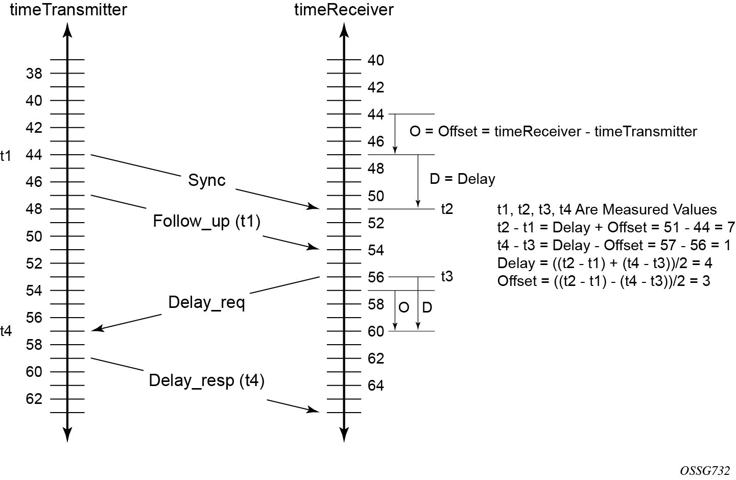
The basic synchronization timing computation between the PTP timeReceiver and PTP timeTransmitter is shown in Figure: PTP timeReceiver and timeTransmitter time synchronization computation. This figure illustrates the offset of the timeReceiver clock referenced to the best timeTransmitter signal during startup.
When using IEEE 1588v2 for distribution of a frequency reference, the timeReceiver calculates a message delay from the timeTransmitter to the timeReceiver based on the timestamps exchanged. A sequence of these calculated delays contain information of the relative frequencies of the timeTransmitter clock and timeReceiver clock but has a noise component related to the packet delay variation (PDV) experienced across the network. The timeReceiver must filter the PDV effects so as to extract the relative frequency data and then adjust the timeReceiver frequency to align with the timeTransmitter frequency.
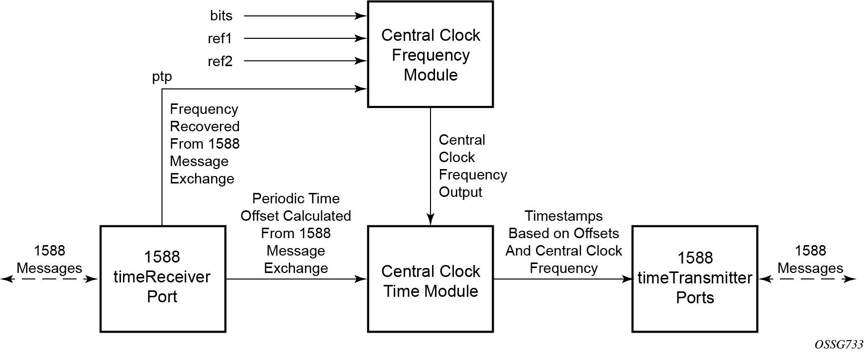
When using IEEE 1588v2 for distribution of time, the 7750 SR and 7450 ESS use the four timestamps exchanged using the IEEE 1588v2 messages to determine the offset between the router time base and the external timeTransmitter clock time base. The router determines the offset adjustment and then in between these adjustments, the router maintains the progression of time using the frequency from the central clock of the router. This allows time to be maintained using a BITS input source or a Synchronous Ethernet input source even if the IEEE 1588v2 communications fail. When using IEEE 1588v2 for time distribution, the central clock should at a minimum have a system timing input reference enabled. Figure: Using IEEE 1588v2 for time distribution displays how IEEE 1588v2 is used for time distribution.