Multi-chassis stateless NAT redundancy is based on a switchover of the NAT pool that can assume active (master) or standby state. The inside/outside routes that attract traffic to the NAT pool are always advertised from the active node (the node on which the pool is active).
This dual-homed redundancy based on the pool mastership state works well in scenarios where each inside routing context is configured with a single NAT policy (NAT’d traffic within this inside routing context is mapped to a single NAT pool).
However, in cases where the inside traffic is mapped to multiple pools (with deterministic NAT and in case when multiple NAT policies are configured per inside routing context), the basic per pool multi-chassis redundancy mode can cause the inside traffic within the same routing instance to fail because some pools referenced from the routing instance may be active on one node while other pools may be active on the other node.
Imagine a case where traffic ingressing the same inside routing instance is mapped as follows (this mapping can be achieved via filters):
Source ip-address A → Pool 1 (nat-policy 1) active on Node 1
Source ip-address B → Pool 2 (nat-policy 2) active on Node 2
Traffic for the same destination is normally attracted only to one NAT node (the destination route is advertised only from a single NAT node). Assume that this node is Node 1 in the example. After the traffic arrives to the NAT node, it is mapped to the corresponding pool according to the mapping criteria (routing based or filter based). But if active pools are not co-located, traffic destined for the pool that is active on the neighboring node would fail. In our example traffic from the source ip-address B would arrive to the Node 1, while the corresponding Pool 2 is inactive on that node. Consequently the traffic forwarding would fail.
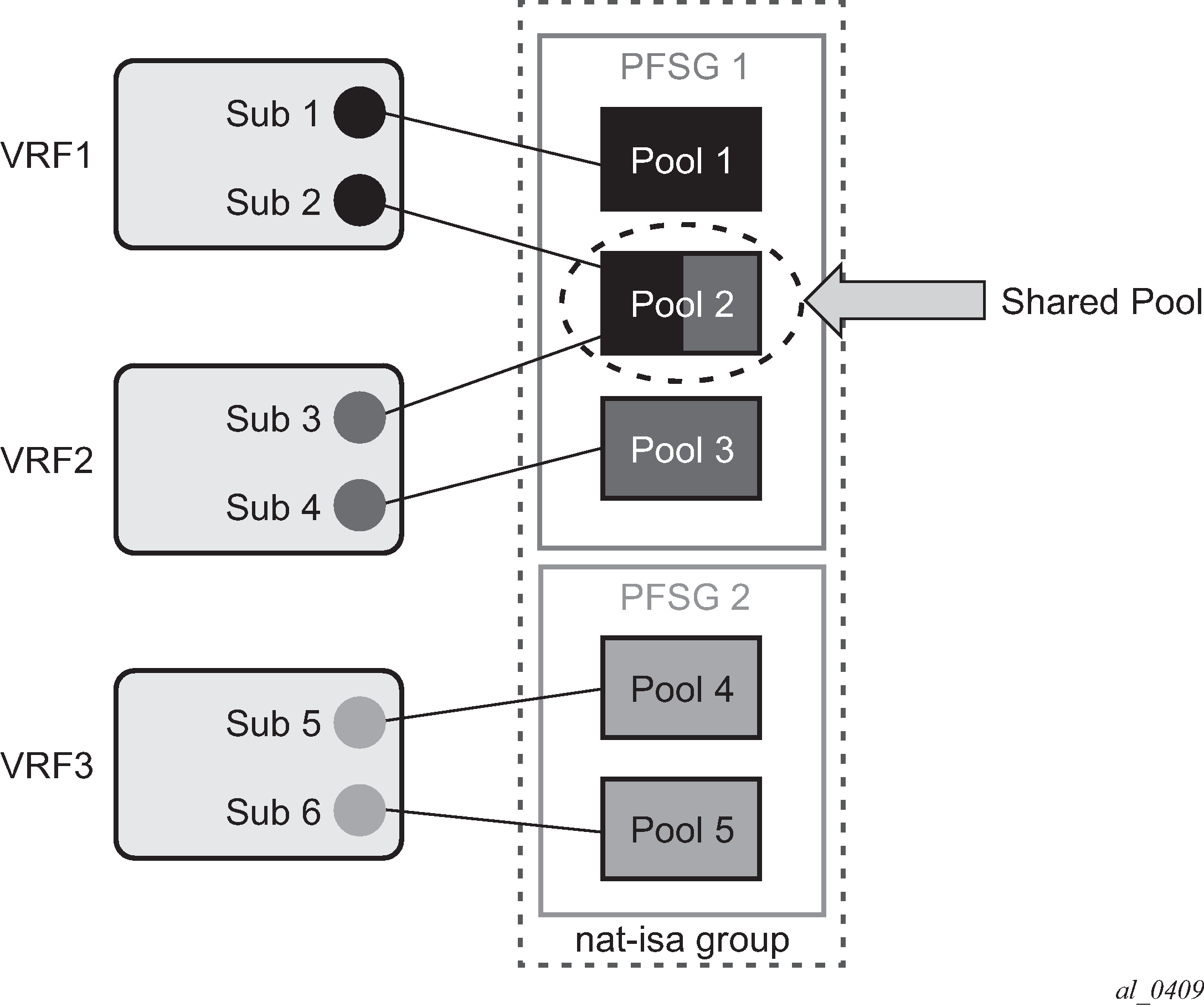
To remedy this situation, a group of pools targeted from the same inside routing context must be active on the same node simultaneously. In other words, the active pools referenced from the same inside routing instance must be co-located. This group of pools is referred to as Pool Fate Sharing Group (PFSG). The PFSG is defined as a group of all NAT pools referenced by inside routing contexts whereby at least one of those pools is shared by those inside routing contexts. This is shown in Figure: Active-Standby intra-chassis redundancy model.
Even though only Pool 2 is shared between subscribers in VRF 1 and VRF 2, the remaining pools in VRF 1 and VRF 2 must be made part of PFSG 1 as well.
This ensures that the inside traffic is always mapped to pools that are active in a single box.
Figure: Pool fate sharing group shows the pool fate sharing group.

There is always one lead pool in PFSG. The Lead pool is the only pool that is exporting/monitoring routes. Other pools in the PFSG are referencing the lead pool and they inherit its (activity) state. If any of the pools in PFSG fails, all the pools in the PFSG switch the activity, or in another words they share the fate of the lead pool (active/standby/disabled).
There is one lead pool per PFSG per node in a dual-homed environment. Each lead pool in a PFSG has its own export route that must match the monitoring route of the lead pool in the corresponding PFSG on the peering node.
PFSG is implicitly enabled by configuring multiple pools to follow the same lead pool.